
Quenching and tempering building furnace

A quenching, tempering, and tempering furnace technology, applied in the field of heat treatment, can solve the problems of thermal energy waste, heat dissipation, and discharge outside the furnace, and achieve the effect of ensuring temperature uniformity, reducing heat dissipation, and saving floor space.

Inactive Publication Date: 2019-09-17
SHANDONG LIANMEI SPRINGS TECH CORP
View PDF0 Cites 2 Cited by
  • Summary
  • Abstract
  • Description
  • Claims
  • Application Information

AI Technical Summary

Problems solved by technology

At present, the heating furnace and tempering furnace for metal quenching generally adopt industrial gas furnaces. The working principle of industrial gas furnaces is that high-pressure air is used to support high-pressure gas to generate heat, and at the same time discharge a large amount of exhaust gas, especially the temperature of exhaust gas from box-type furnaces. The temperature is almost isothermal, and a large amount of heat will be discharged out of the furnace with the exhaust gas; in addition, the temperature difference between the surface temperature of the furnace body and the ambient air temperature is 40-45°C, so the surface of the furnace body will also lose heat, and the total heat loss is generally 70-75%. , that is, the utilization rate of heat energy actually applied to the workpiece is only about 25-30%, which will cause a great waste of heat energy, and the waste heat discharged will cause serious pollution to the surrounding environment

Method used


Image

  • Quenching and tempering building furnace
  • Quenching and tempering building furnace
  • Quenching and tempering building furnace

Examples


Embodiment 1

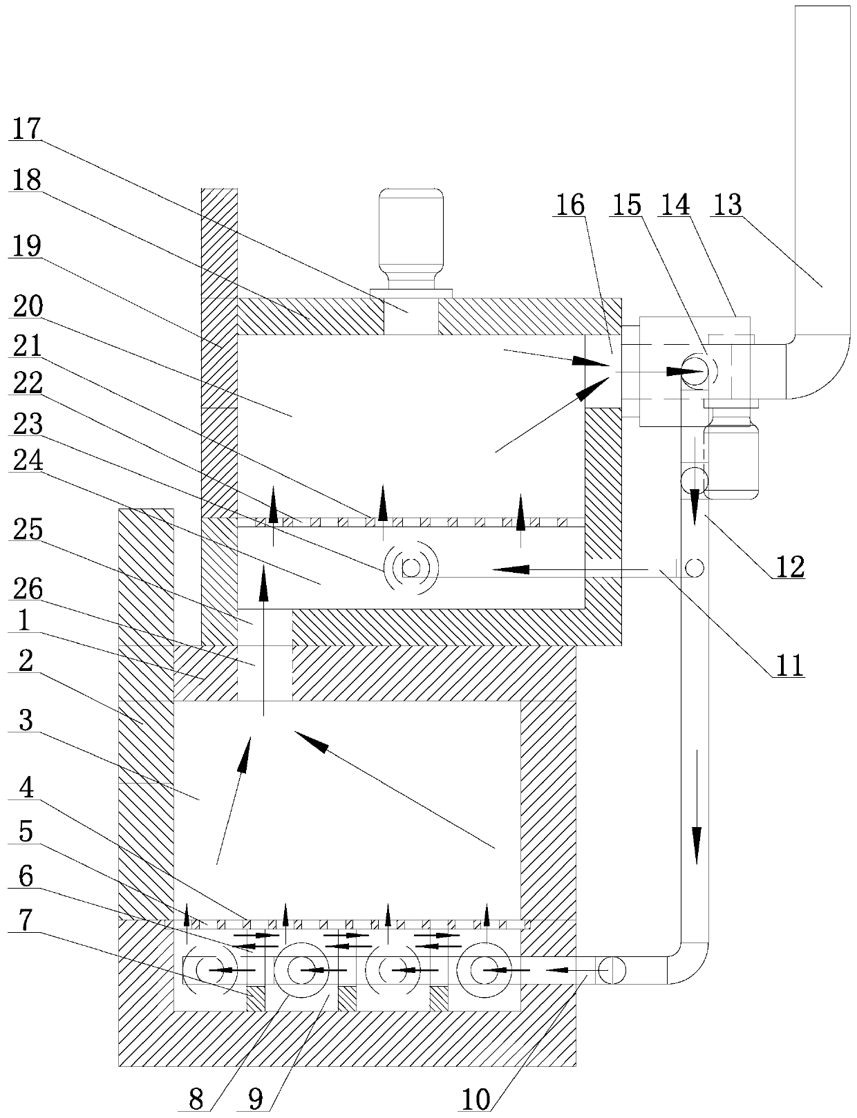
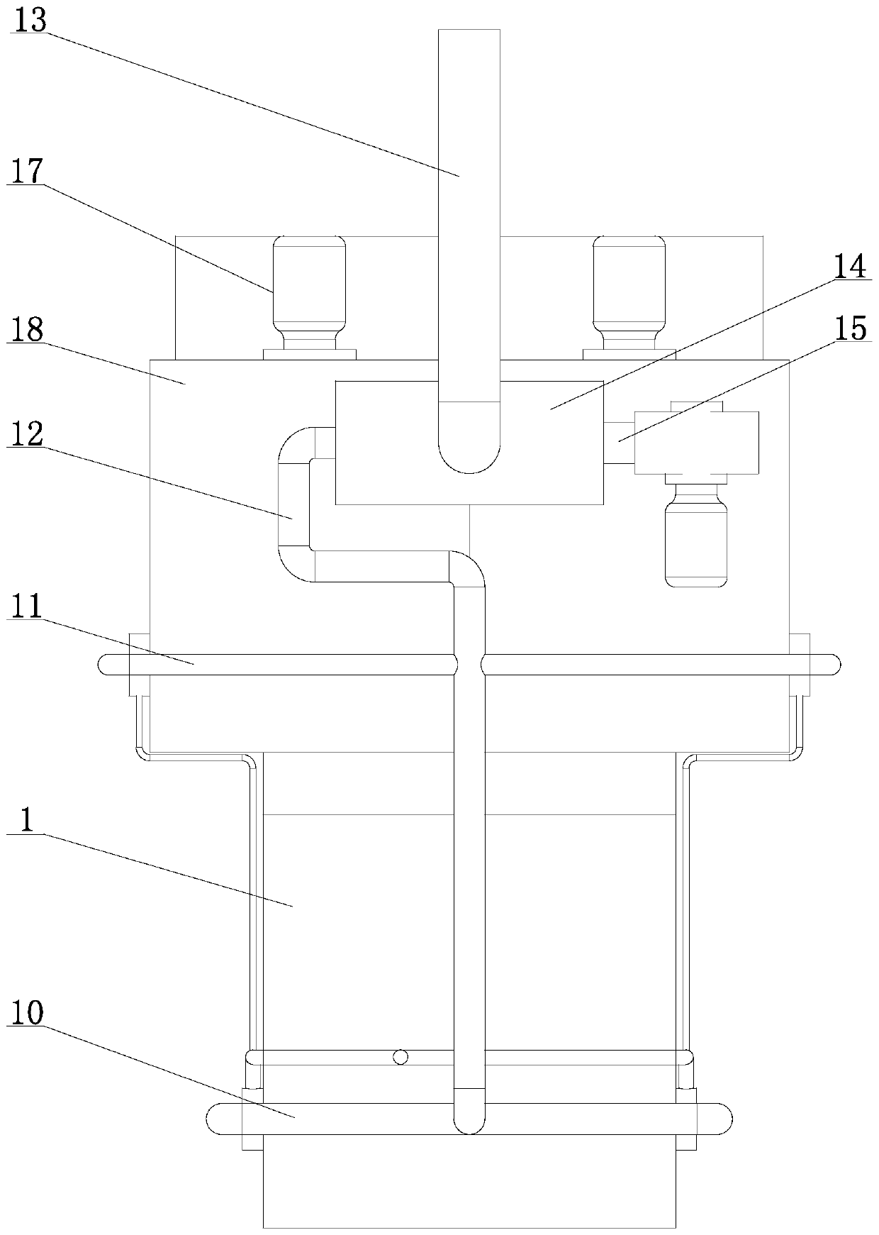
[0034] Such as figure 1 , 2 As shown, in the quenching and tempering building furnace in the present embodiment, the tempering furnace 18 is arranged on the top of the quenching furnace 1, the outlet of the chimney 26 of the quenching furnace 1 is arranged on the top of the quenching furnace 3, and the furnace bottom of the tempering furnace 18 is provided with the quenching furnace. The chimney 26 outlet of the chimney 1 corresponds to the air inlet 25, and the chimney 26 outlet is directly connected to the air inlet 25 at the furnace bottom of the tempering furnace 18.

[0035] By placing the tempering furnace 18 on the top of the quenching furnace 1, the floor space is saved; connecting the quenching furnace 1 and the tempering furnace 18 can make the high-temperature flue gas discharged from the exit of the chimney 26 of the quenching furnace 1 go upward to the intake air at the bottom of the tempering furnace 18 port 25, all the waste heat of the exhaust gas in the quenc...

Embodiment 2

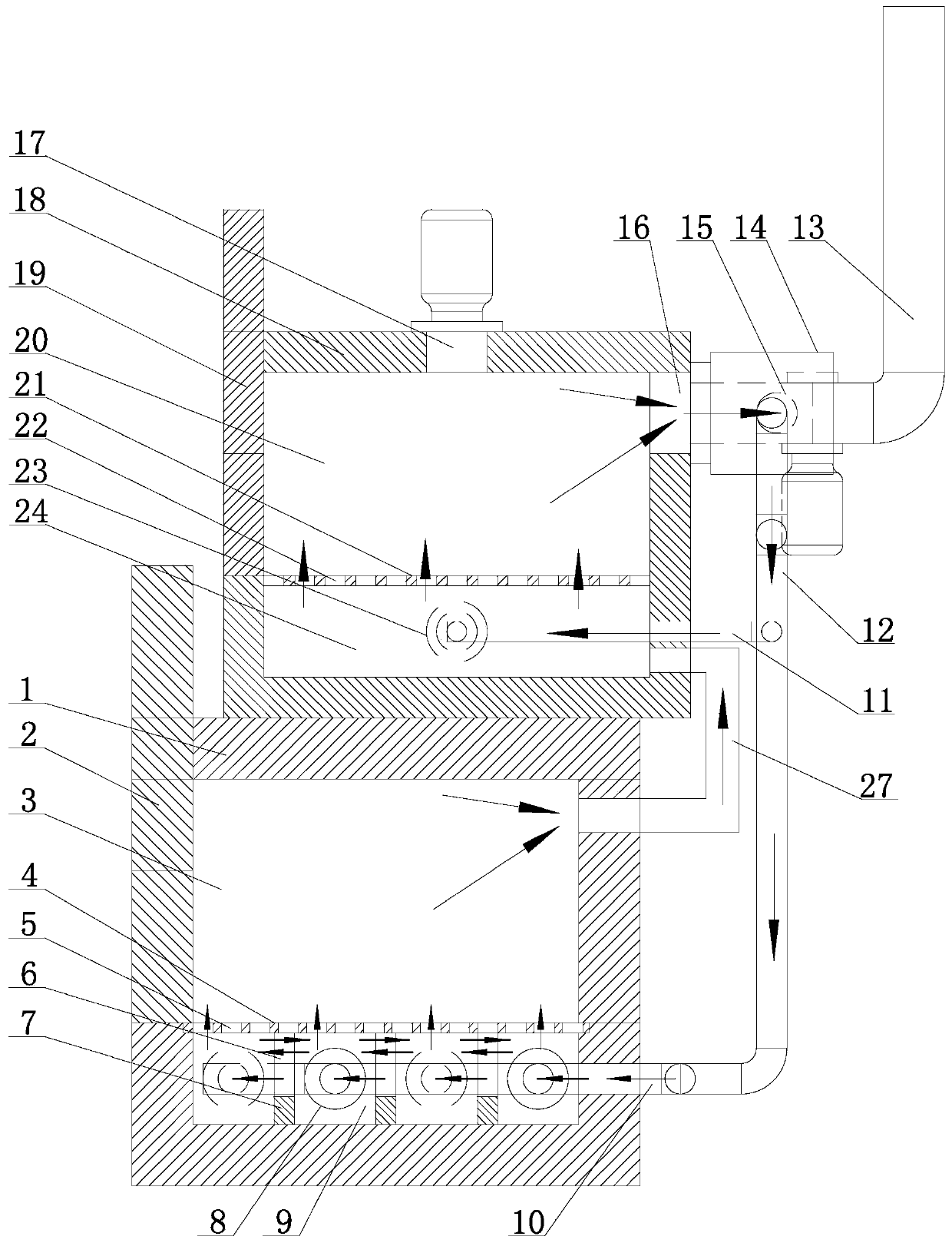
[0044] Such as image 3 As shown, in the quenching and tempering building furnace in the present embodiment, the tempering furnace 18 is arranged on the top of the quenching furnace 1, and the outlet of the chimney 26 of the quenching furnace 1 is arranged on the furnace wall on the right side of the quenching furnace 3, and the same side of the tempering furnace 18 The furnace wall (i.e. the right furnace wall) is provided with an air inlet 25 corresponding to the outlet of the chimney 26 of the quenching furnace 1, and the outlet of the chimney 26 is communicated with the air inlet 25 of the tempering furnace 18 through a pipeline 27, that is, the outlet of the quenching furnace The high-temperature flue gas discharged from the chimney 26 is discharged into the tempering furnace 18 through the pipe 27. Other structures are the same as in Embodiment 1. In this embodiment, all the waste heat of the exhaust gas from the quenching furnace will also be discharged into the temper...


PUM


Abstract

The invention relates to a quenching and tempering building furnace, which is mainly used for the metal heat treatment industry and belongs to the field of heat treatment. The quenching and tempering building furnace is characterized in that a tempering furnace is arranged at the top of a quenching furnace, and a chimney outlet of the quenching furnace communicates with a gas inlet of the tempering furnace. The quenching furnace and the tempering furnace communicate together, and high-temperature flue gas discharged from the chimney outlet of the quenching furnace can be introduced into the tempering furnace through the gas inlet of the tempering furnace, and is used for heating tempering workpieces so as to achieve the purpose of secondary utilization of waste heat; the tempering furnace is arranged at the top of the quenching furnace, and the distance from the top of the quenching furnace to the bottom of the tempering furnace is only equal to one partition wall between two furnace chambers; meanwhile, the whole tempering furnace is wrapped by hot air emitted upwards by the periphery of the lower quenching furnace, thus reducing the heat of the surface of the tempering furnace. According to the quenching and tempering building furnace, the heat energy utilization rate can be improved to 37%, and the energy consumption is saved by about 26%, thus reducing the production cost and achieving the effect of protecting the atmospheric environment.

Description

technical field [0001] The invention relates to a quenching and tempering furnace, which is mainly used in the metal heat treatment industry and belongs to the field of heat treatment. Background technique [0002] The temperature of the heating furnace used for metal quenching is generally about 870°C, and the temperature of the tempering furnace is generally about 470°C. At present, the heating furnace and tempering furnace for metal quenching generally adopt industrial gas furnaces. The working principle of industrial gas furnaces is that high-pressure air is used to support high-pressure gas to generate heat, and at the same time discharge a large amount of exhaust gas, especially the temperature of exhaust gas from box-type furnaces. The temperature is almost isothermal, and a large amount of heat will be discharged out of the furnace with the exhaust gas; in addition, the temperature difference between the surface temperature of the furnace body and the ambient air tem...

Claims


Application Information

Patent Timeline
Patent Type & Authority Applications(China)
IPC IPC(8): C21D9/00C21D1/62C21D1/18
CPCC21D1/18C21D1/62C21D9/00
Inventor 冯以盛
Owner SHANDONG LIANMEI SPRINGS TECH CORP
Learn More