Flying wing layout solar unmanned aerial vehicle

A solar unmanned aerial vehicle and layout technology, applied in the field of flying wing layout solar unmanned aerial vehicle, can solve the problems of increasing the structural weight of the whole machine, weak wind resistance of the unmanned aerial vehicle, increasing the weight of the whole machine cable, etc. The overall performance is improved, the difficulty of aerodynamic design is reduced, and the structural weight is saved.

Pending Publication Date: 2019-09-20
CHINA ACAD OF AEROSPACE AERODYNAMICS
View PDF0 Cites 8 Cited by
  • Summary
  • Abstract
  • Description
  • Claims
  • Application Information

AI Technical Summary

Problems solved by technology

Conventional layout of solar UAVs has the following disadvantages: (1) The lift coefficient is large, and the flight speed under the same wing load condition is low, resulting in weak wind resistance of UAVs; (2) The fuselage increases the wetted area of ​​the whole aircra

Method used


Image

  • Flying wing layout solar unmanned aerial vehicle
  • Flying wing layout solar unmanned aerial vehicle
  • Flying wing layout solar unmanned aerial vehicle

Examples


Embodiment Construction

[0038] In order to make the object, technical solution and advantages of the present invention clearer, the embodiments disclosed in the present invention will be further described in detail below in conjunction with the accompanying drawings.

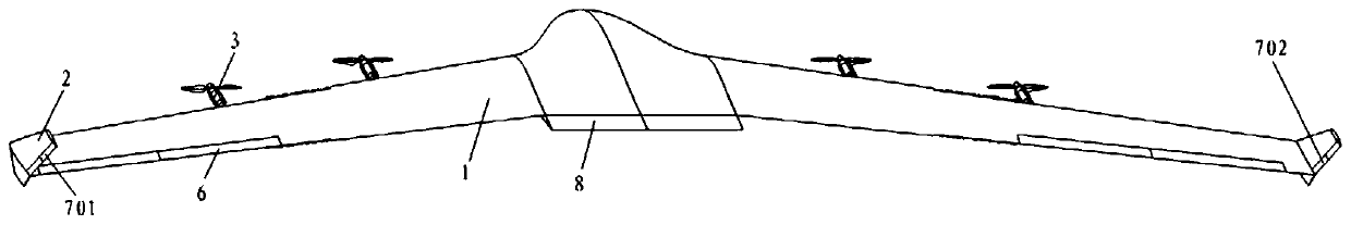
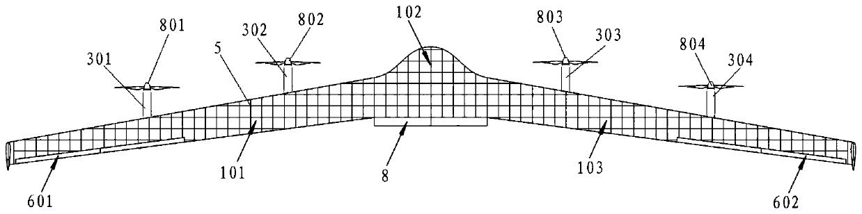
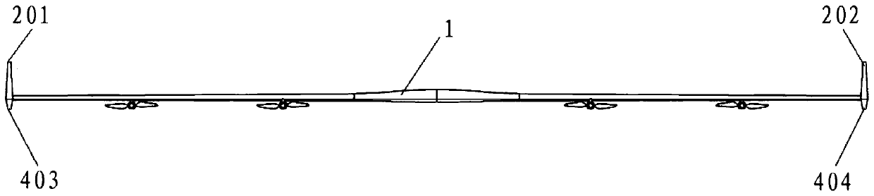
[0039] Such as Figure 1~4 , in this embodiment, the flying wing layout solar UAV includes: wing 1, vertical tail 2, power pod 3, non-retractable landing gear 4, control surface and solar cell array 5, wherein the control The mask body can include: aileron 6, rudder 7 and full-motion horizontal tail 8. Among them, the vertical tail 2 adopts a trapezoidal shape and is arranged on the wingtips on both sides of the wing 1; the full-motion horizontal tail 8 adopts a rectangular shape and is arranged at the tail of the middle section of the wing 1; the aileron 6 is arranged on the rear edge of the wing 1; The rear edge of the tail 2; the power pod 3 is hung under the wing 1; the solar battery array 5 is laid on the upper surface of the win...


PUM


Abstract

The invention discloses a flying wing layout solar unmanned aerial vehicle. The flying wing layout solar unmanned aerial vehicle comprises wings, vertical fins, power pods, non-retractable landing gears, a control surface and a solar cell array, wherein the control surface comprises ailerons, rudders and stabilators; the vertical tails adopt a trapezoidal shape and are arranged at wing tips on the two sides of the wings, the stabilators adopt a rectangular shape and are arranged at the tail parts of the middle sections of the wings, the ailerons are arranged at the trailing edges of the wings, the rudders are arranged at the trailing edges of the vertical fins; the power pods are hung below the wings, the solar cell array is laid on the upper surfaces of the wings, the non-retractable landing gears are arranged below the whole flying wing layout solar unmanned aerial vehicle. According to the unmanned aerial automobile, the scale of the unmanned aerial vehicle can be reduced by virtue of a high pneumatic lift-drag ratio and a light structural weight, and the wind resistance capability of the unmanned aerial vehicle is enhanced through the high flight speed.

Description

technical field [0001] The invention belongs to the technical field of overall design of unmanned aerial vehicles, and in particular relates to a solar unmanned aerial vehicle with flying wing layout. Background technique [0002] Solar UAV is an electric aircraft powered by solar radiation, and it is the product of the combination of aviation science and technology and new energy technology. Solar-powered drones have long cruising time, high flight altitude, wide coverage area, low cost of use, and no pollution to the environment. They can perform various tasks such as communication relay, electronic reconnaissance, and mobile networking. It is an important supplement to flying platforms such as airplanes and high-altitude airships, and has received widespread attention at home and abroad. [0003] Most of the existing solar-powered drones at home and abroad adopt the conventional layout of "wing + fuselage + tail", represented by the "Zephyr" series of the British company...

Claims


Application Information

Patent Timeline
IPC IPC(8): B64C39/10B64D27/24B64D29/02
CPCB64C39/10B64D27/24B64D29/02B64D2211/00B64U10/25B64U50/19B64U50/13
Inventor 张凯佟阳刘峰吴伟伟
Owner CHINA ACAD OF AEROSPACE AERODYNAMICS
Why Eureka
Try Eureka