Supercharge Your Innovation With Domain-Expert AI Agents!

Full-automatic steel ladle argon connecting device

A fully automatic, ladle technology, which is applied in the direction of casting molten material containers, manufacturing tools, metal processing equipment, etc., can solve the problems of low connection success rate, short operation time, heavy maintenance workload, etc., to reduce the movement resistance of the cylinder, and quickly Easy replacement and installation, maintenance and inspection

Active Publication Date: 2019-09-20
武汉钢铁有限公司
View PDF3 Cites 3 Cited by
  • Summary
  • Abstract
  • Description
  • Claims
  • Application Information

AI Technical Summary

Problems solved by technology

[0004] At present, there are mainly three types of argon-blowing connectors: manual quick connector, bell-type automatic connector, and flat-plate automatic connector. Among them, the manual quick connector has the advantages of simple equipment and high connection rate, but because of the manual connection, the working time Long, the working environment is harsh, and it is easy to be damaged by ladle slag during operation, and the trolley is not stable, and it is easy to sprain, causing personal injury; The male head is matched with automatic connection, which has the advantages of automatic connection, short working time, personnel do not need to get on the car, and guarantees life safety. However, there are many equipment accessories, which are easy to collide and slag. The impact load is relatively high, so the equipment failure rate is high, the connection success rate is low, and the maintenance workload is large; although the flat automatic joint type can realize fully automatic connection, its sealing ring is not heat-resistant and has a high failure rate, and This method has high requirements on the cleanliness of the reference plane of the trolley. Once there is sticky residue on the reference plane, the system will not be able to automatically connect argon.

Method used


Image

  • Full-automatic steel ladle argon connecting device
  • Full-automatic steel ladle argon connecting device
  • Full-automatic steel ladle argon connecting device

Examples


Embodiment Construction

[0031] In order to better understand the present invention, the present invention will be further described below in conjunction with the accompanying drawings and specific embodiments.

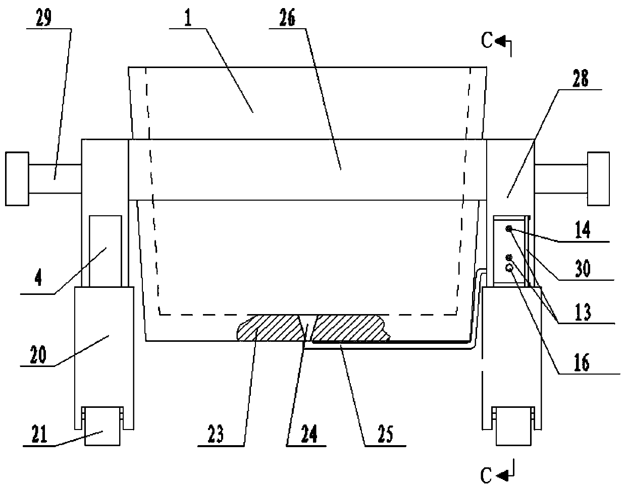
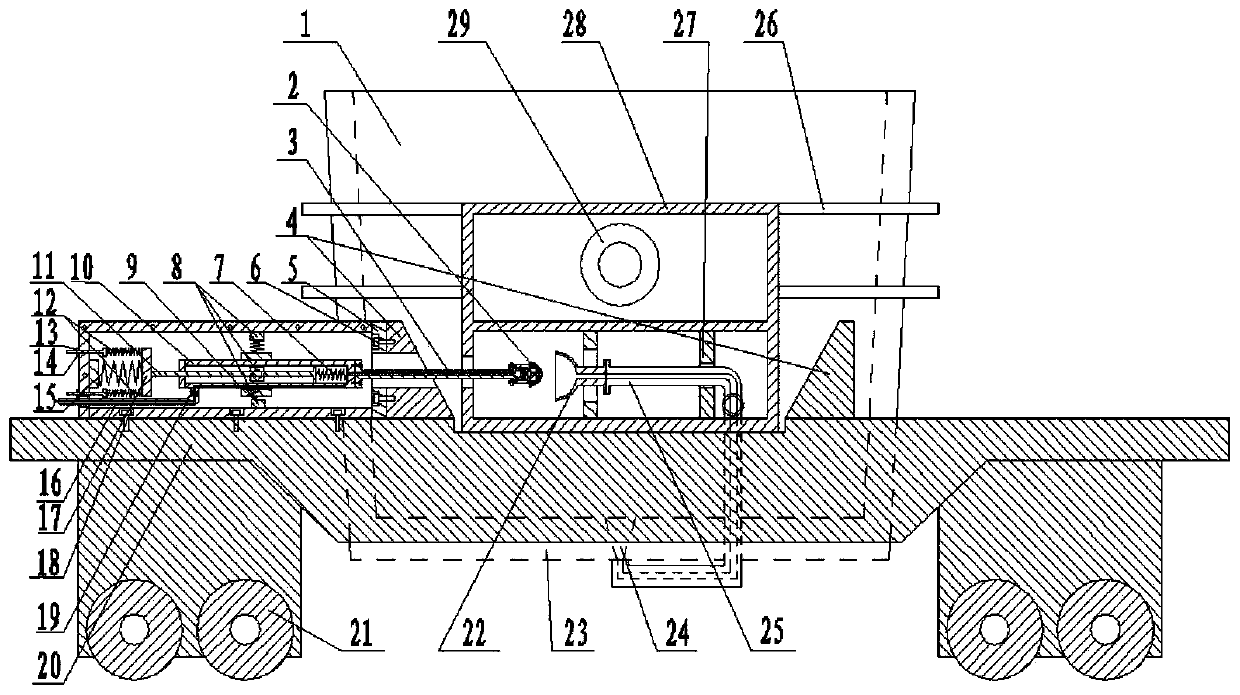
[0032] Such as figure 1 and figure 2 A fully automatic argon receiving device for a ladle is shown, comprising a ladle car, a ladle 1, and a horizontal follow-up argon receiving system, two opposite guide plates 4 are provided on both sides of the ladle car; the ladle 1 passes through The saddles 28 on both sides are installed on the ladle car, and the saddle 28 is located between the two guide plates 4 on the same side; the horizontal follow-up argon connection system is installed on one side of the guide plate 4 of the ladle car Above, the gas outlet end of the horizontal follow-up argon connection system communicates with the injection hole 24 provided at the inner bottom of the ladle 1 through a pipeline.

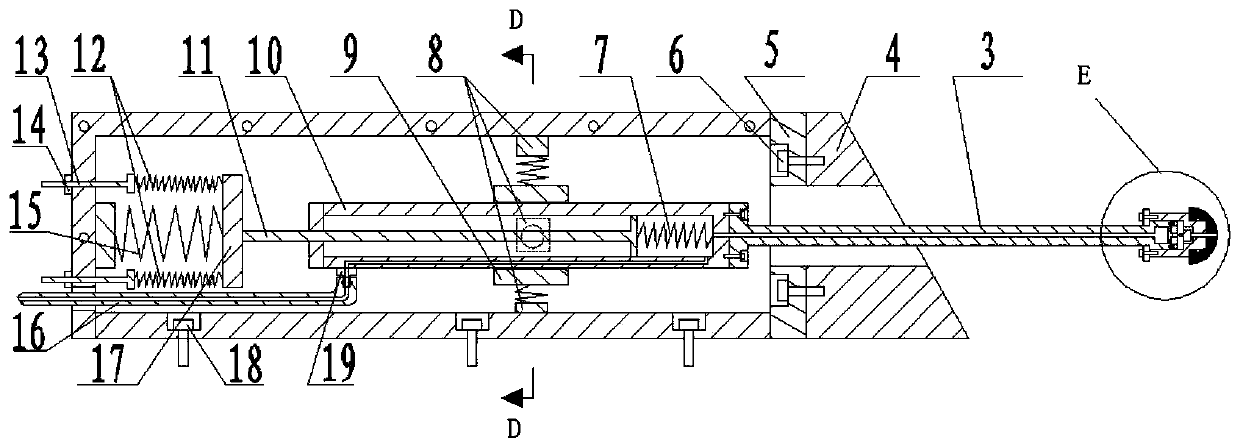
[0033] Preferably, as image 3 As shown, the horizontal follow-up argon connec...


PUM


Abstract

The invention discloses a full-automatic steel ladle argon connecting device. The device comprises a steel ladle car, a steel ladle, and a horizontal follow-up type argon connecting system, wherein two opposite guide plates are arranged on each side of the steel ladle car respectively, the steel ladle is installed on the steel ladle car through saddle seats on the two sides, each saddle seat is arranged between the two guide plates on the same side, the horizontal follow-up type argon connecting system is arranged on one side guide plates of the steel ladle car, and a gas outlet end of the horizontal follow-up type argon connecting system communicates with a spraying and blowing hole formed in the bottom of the steel ladle through a pipeline. The device has the beneficial effects that the overall system is simple in structure, capable of being used in various severe working conditions, low in cost, stable and reliable in operation, and the problems that an existing steel ladle argon connecting device is large in impact and frequent in fault is effectively solved.

Description

technical field [0001] The invention relates to the technical field of steelmaking, in particular to a fully automatic argon connection device and method for a ladle. Background technique [0002] Ladle argon blowing treatment, also known as molten steel argon blowing treatment, is a simple out-of-furnace refining method for degassing molten steel and removing non-metallic inclusions. It has the following important metallurgical significance: 1. Reduce the gas dissolved in molten steel ( Such as hydrogen, nitrogen, oxygen) content; 2. Remove non-metallic inclusions (such as oxides, sulfides, nitrides, etc.) remaining in molten steel; 3. Make the composition and temperature of molten steel uniform before pouring, which can be obviously Lower the opening temperature of pouring. [0003] The argon blowing system at the bottom of the ladle includes the following configurations: ventilation bricks at the bottom of the ladle, piping for the ladle body, argon blowing connection de...

Claims


Application Information

Patent Timeline
IPC IPC(8): C21C7/072B22D41/00
CPCB22D41/00C21C7/072
Inventor 宋泽啟杨新泉陈新元刘洋陈立向忠辉付刚强
Owner 武汉钢铁有限公司
Features
  • R&D
  • Intellectual Property
  • Life Sciences
  • Materials
  • Tech Scout
  • Unparalleled Data Quality
  • Higher Quality Content
  • 60% Fewer Hallucinations
Learn More