Supercharge Your Innovation With Domain-Expert AI Agents!

Real-time monitoring method and device for laser cladding

A real-time monitoring and laser cladding technology, applied in measurement devices, metal material coating processes, instruments, etc., can solve the problems of waste of resources, fluctuations in cladding quality, and low measurement accuracy, and achieve the goal of improving work efficiency and quality. Effect

Active Publication Date: 2021-10-29
成都绝影智能科技有限公司
View PDF4 Cites 0 Cited by
  • Summary
  • Abstract
  • Description
  • Claims
  • Application Information

AI Technical Summary

Problems solved by technology

[0002] The process quality of laser cladding is related to the distance (defocus) and tilt attitude of the laser relative to the substrate material. In order to ensure a stable cladding effect, the laser spot is required to be correctly focused on the cladding area at a certain angle (usually a vertical angle). During the cladding process, since the laser head moves relatively along the surface of the workpiece, the working distance may change, so that the projected laser spot cannot be correctly focused on the cladding area, or the laser spot cannot be projected to the base surface at the correct angle. , that is, a certain inclination will eventually lead to fluctuations in cladding quality
The general solution is to install a ranging sensor (such as a laser displacement sensor) next to the laser to ensure that the laser is always at the best working distance, but the ranging sensor is often easily interfered by laser or cladding spatter, and can only measure a certain distance. The distance from a fixed position on the laser to a certain point on the surface of the workpiece cannot simultaneously feed back the inclination angle of the laser relative to the surface of the workpiece. Therefore, it is difficult for general ranging sensors to simultaneously solve the problem of real-time measurement of the working distance and inclination angle of the laser.
[0003] After the laser cladding is completed, it is generally necessary to perform secondary processing on the cladding surface to make the surface meet certain size requirements and roughness requirements. Rare metal powder materials are relatively expensive. If the cladding layer is too thick, it will cause resource loss. Waste, in order to ensure cladding quality, control costs, and improve cladding efficiency, it is necessary to accurately measure and control the thickness of the cladding layer in real time
The traditional methods of measuring the thickness of laser cladding layer include metallographic method, ultrasonic method, etc., but the metallographic method will destroy the overall performance of the cladding layer, and it is a sampling test, which does not have real-time performance; the ultrasonic method has certain measurement blind spots, and the measurement accuracy is not high.

Method used


Image

  • Real-time monitoring method and device for laser cladding
  • Real-time monitoring method and device for laser cladding
  • Real-time monitoring method and device for laser cladding

Examples


Embodiment

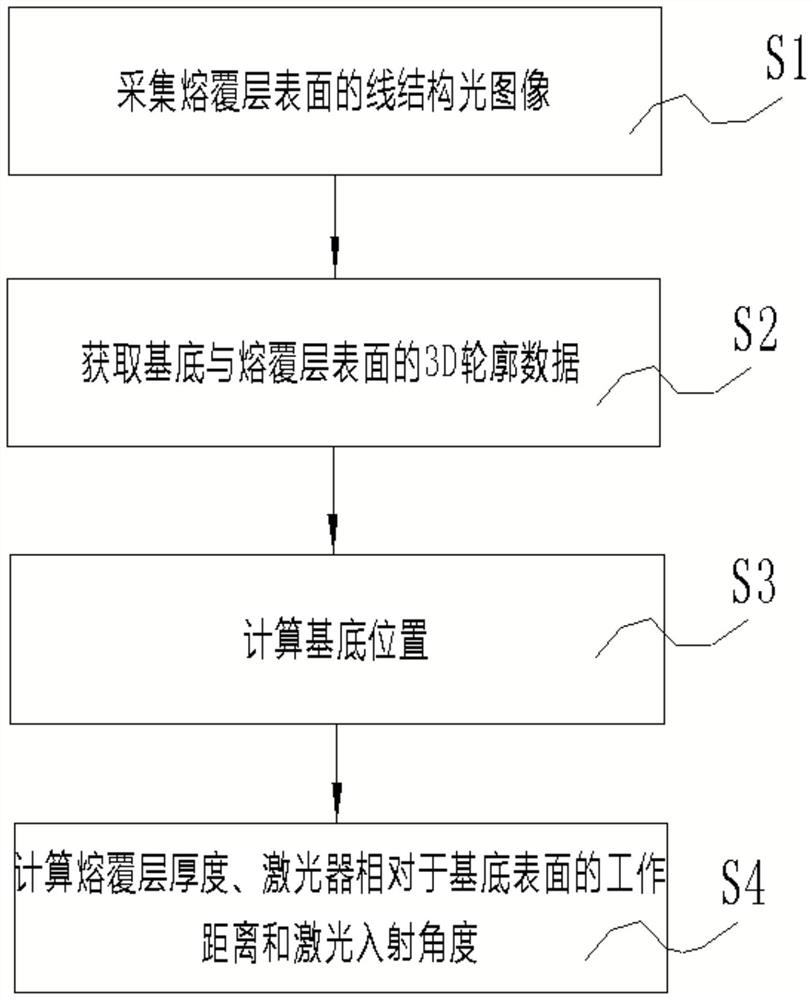
[0063] Such as Figure 1-Figure 7 As shown, a real-time monitoring method for laser cladding, including the following steps:

[0064] A real-time monitoring method for laser cladding, comprising the steps of:

[0065] S1. Collecting a line structured light image on the surface of the cladding layer. An alternative solution is to project the measurement laser of the laser profiler onto the surface of the substrate and cladding layer based on the triangulation principle of line structured light. The laser profiler is fixedly installed relative to the cladding laser, and the measuring laser emitted by the laser profiler is aimed at the cladding area near the cladding laser spot before starting the cladding. If the cladding laser spot is close to a rectangular shape, a more preferred installation position is to make the laser line of the laser profiler parallel to the long axis of the cladding laser spot, 10-25mm away from the center of the cladding area, and try to make the Th...


PUM


Abstract

The invention discloses a real-time monitoring method and device for laser cladding. The method comprises the following steps: collecting a line structured light image on the surface of the cladding layer; acquiring 3D profile data of the substrate and the surface of the cladding layer; calculating the position of the substrate ; Calculate cladding layer thickness, working distance of laser relative to substrate surface and laser incident angle. The invention can measure the working distance of the laser relative to the surface of the substrate, the laser incident angle, the thickness of the cladding layer and defects in real time, and can adjust relevant process parameters in real time, stably control the thickness of the cladding layer, improve the quality of laser cladding, and improve the working efficiency at the same time. efficiency.

Description

technical field [0001] The invention relates to the technical field of laser cladding, in particular to a real-time monitoring method and device for laser cladding. Background technique [0002] The process quality of laser cladding is related to the distance (defocus) and tilt attitude of the laser relative to the substrate material. In order to ensure a stable cladding effect, the laser spot is required to be correctly focused on the cladding area at a certain angle (usually a vertical angle). During the cladding process, since the laser head moves relatively along the surface of the workpiece, the working distance may change, so that the projected laser spot cannot be correctly focused on the cladding area, or the laser spot cannot be projected to the base surface at the correct angle. , that is, a certain inclination will eventually lead to fluctuations in cladding quality. The general solution is to install a ranging sensor (such as a laser displacement sensor) next to...

Claims


Application Information

Patent Timeline
Patent Type & Authority Patents(China)
IPC IPC(8): C23C24/10G01D21/02
CPCC23C24/103G01D21/02
Inventor 张明勇
Owner 成都绝影智能科技有限公司
Features
  • R&D
  • Intellectual Property
  • Life Sciences
  • Materials
  • Tech Scout
  • Unparalleled Data Quality
  • Higher Quality Content
  • 60% Fewer Hallucinations
Learn More