

Paste pump
A paste and pumping technology, which is applied in the direction of pumps, pump components, variable capacity pump components, etc., can solve the problems of difficult feeding, dirty working environment, and large space occupation, so as to reduce labor and site requirements, and improve the overall efficiency of the machine Simple structure and high pumping efficiency
- Summary
- Abstract
- Description
- Claims
- Application Information
AI Technical Summary
Problems solved by technology
Method used
Image

Examples
Embodiment 1
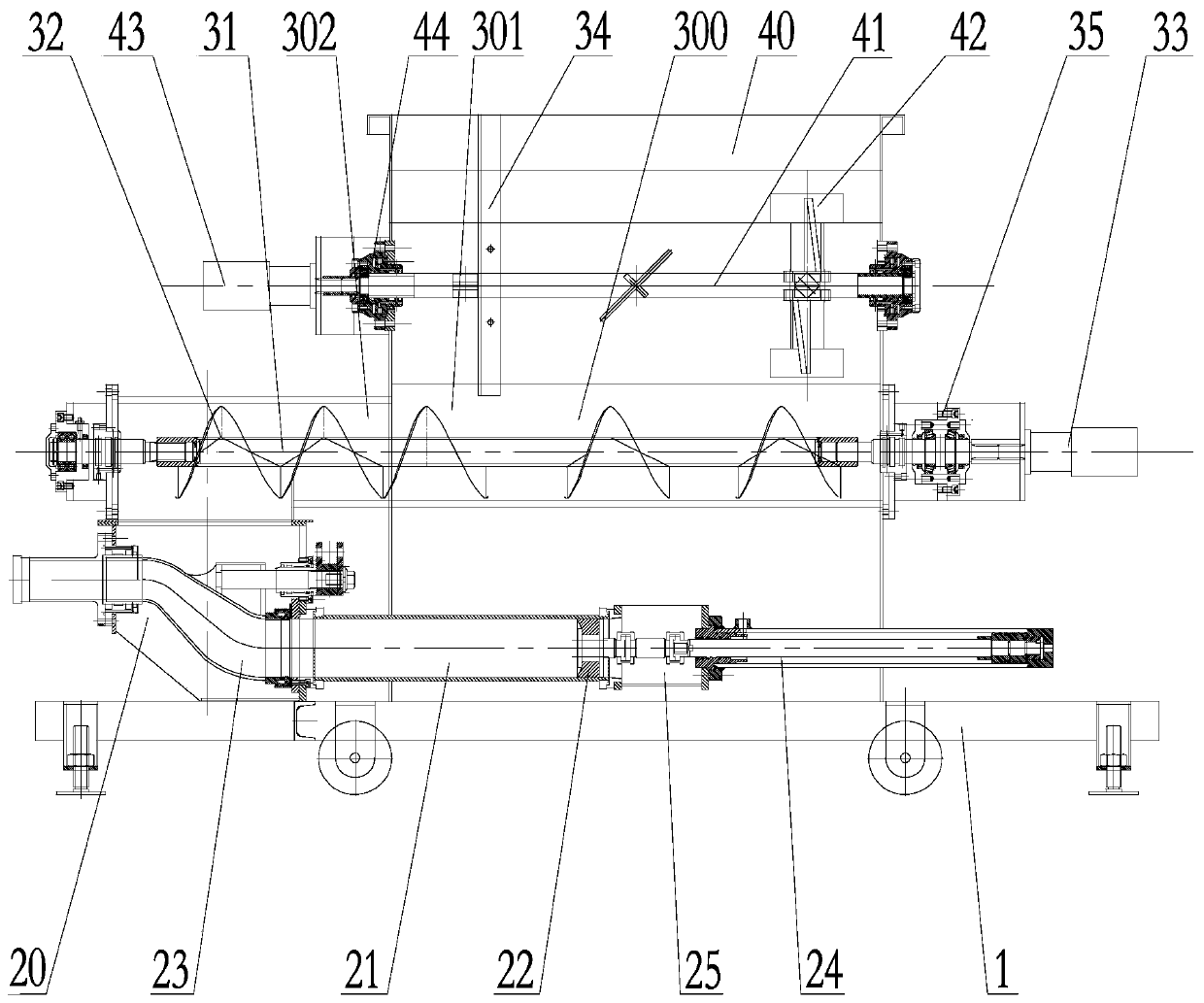
[0036] Such as figure 1 A slurry pump shown includes a frame 1 , a pumping unit 2 , a screw mud pressing unit 3 and a mud stirring unit 4 . Each unit is described in detail as follows:
[0037] Rack 1 can not only perform support work, but also perform mobile transitions.
[0038] The pumping unit 2 is arranged on the frame 1, and the pumping unit 2 includes a pumping hopper 20, a mud cylinder 21 communicated with the pumping hopper 20, a water tank 22 communicated with the mud cylinder 21, and a pumping hopper 20 communicated with the mud cylinder 21. The distribution reversing valve 23 of the cylinder 21 and the pumping power assembly for pumping out the mud in the mud cylinder 21. Such as figure 1 Shown: the pumping direction of the pumping unit 2 in this embodiment pumps horizontally from left to right. Among them: the distribution reversing valve 23 is an S-pipe distribution valve; the pumping power assembly is an oil cylinder 24 and a piston 25; the mud cylinder 21, ...
Embodiment 2
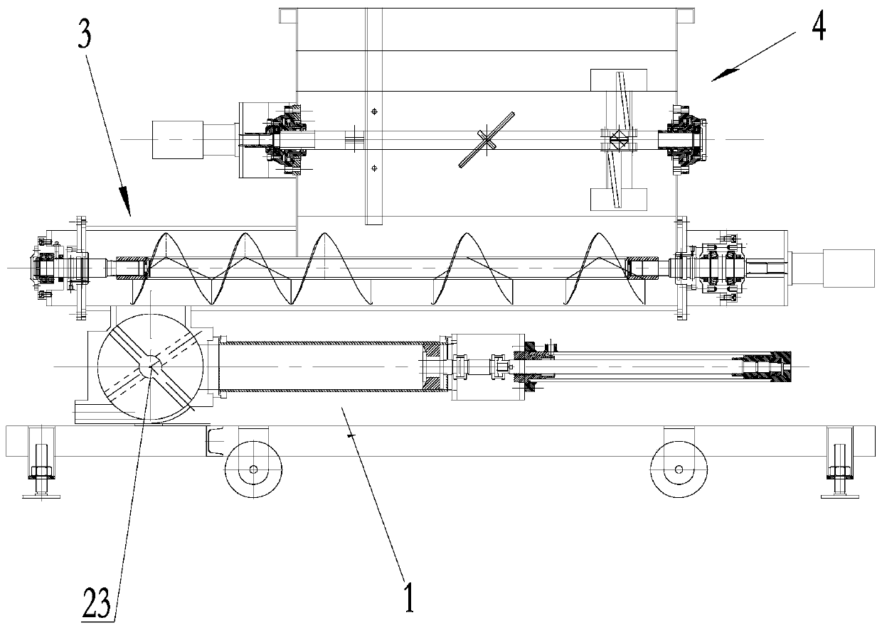
[0046] Such as figure 2 As shown: this embodiment is basically the same as Embodiment 1, the difference is that: in this embodiment: the distributing reversing valve 23 adopts a butterfly plate valve or a cone valve or a ball valve or a gate valve.
Embodiment 3
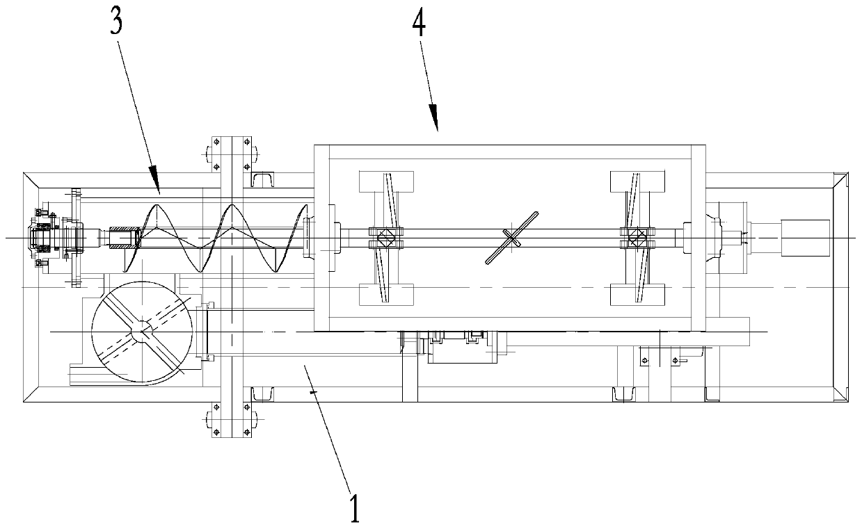
[0048] Such as image 3 As shown: this embodiment is basically the same as Embodiment 1, the difference is that in this embodiment: the screw mud pressing unit 3 is arranged on the side of the pumping unit 2, and the discharge port of the mud pressing hopper is opened at the pressurized The side of the feeding section 302.
PUM
 Abstract
Description
Claims
Application Information