Sampling device and sampling method

A sampling device and sampling machine technology, applied in the direction of sampling devices, etc., can solve the problems of poor stability, complex structure, difficult to adapt to alloy materials, etc., and achieve the effect of smooth sampled parts, easy welding and repair, and good stability

Pending Publication Date: 2019-09-20
国能神福(晋江)热电有限公司 +2
View PDF0 Cites 0 Cited by
  • Summary
  • Abstract
  • Description
  • Claims
  • Application Information

AI Technical Summary

Problems solved by technology

[0006] Existing micro-damage sampling devices mainly use pneumatic cutting, electric spark cutting, and spherical or semi-spherical milling cutter cutting; however, these sampling devices generally have complex structures, poor stability, and insufficient strength of arc-shaped cutters. The operation is inconvenient, the surface of the sampled part is uneven, and it needs to be polished again, and the workload is large; especially for some high-hardness alloy materials, it is difficult to adapt

Method used


Image

  • Sampling device and sampling method
  • Sampling device and sampling method
  • Sampling device and sampling method

Examples


Embodiment 1

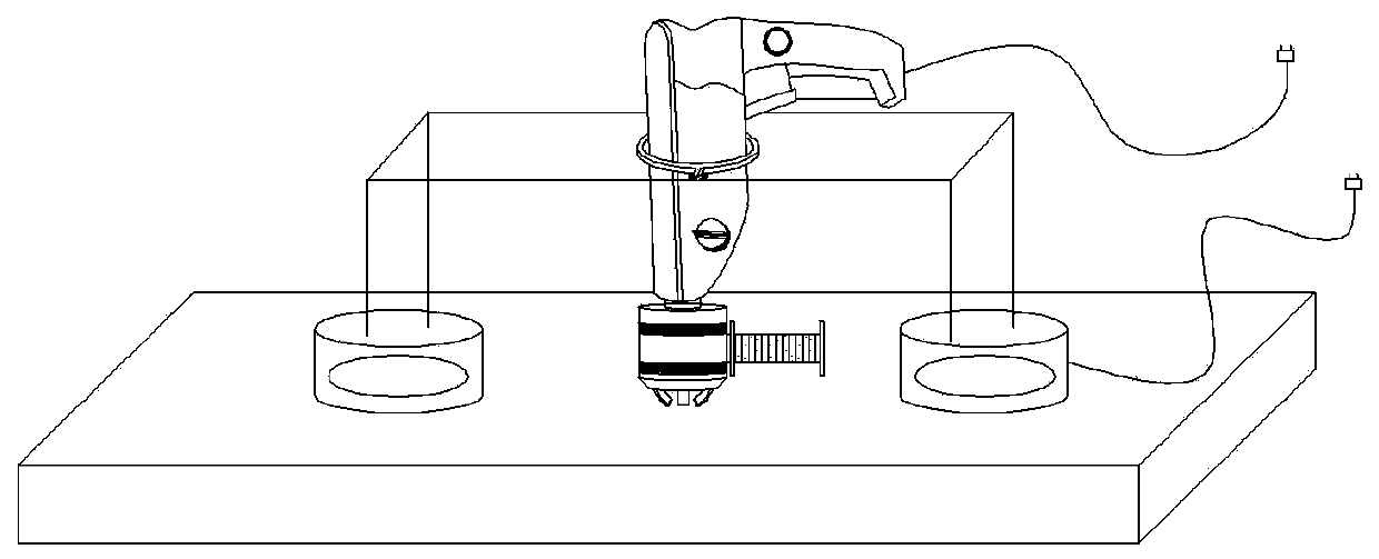
[0040] This embodiment provides a sampling device, such as Figure 1-Figure 6 As shown, it includes a sampling machine and a fixed frame; the sampling machine includes a sampling head and a rotary drive mechanism, the rotary drive mechanism is arranged on the fixed frame, and the fixed frame is provided with a connection mechanism for fixed connection with the member to be sampled.

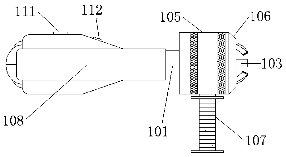
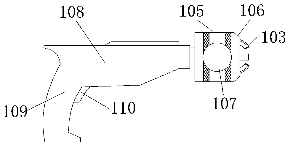
[0041] The sampling head comprises a threaded seat, a rotating seat 102 and a milling cutter 103; the rotating seat is connected with the output shaft of the rotary drive mechanism; the rotating seat 102 is provided with a guide groove corresponding to the milling cutter 103; the milling cutter 103 is arranged on the guide groove, and One side of the axis of rotation; the end of the milling cutter 103 is provided with a blade 116, and the end is facing the axis of rotation; the end of the milling cutter 103 away from the end is the tail end, and the tail end is away from the axis of rotation; the c...

Embodiment 2

[0057] This embodiment provides a magnetic fixing frame, such as Figure 10 As shown, it includes: a bridge-shaped support and a clamping mechanism for clamping the body of the sampler; the bridge-shaped support includes a fixed frame 120 and two support seats; the two support seats are respectively arranged on two opposite sides of the fixed frame 120 end; the top of the support seat is connected to the fixed frame 120, and the bottom of the support seat is provided with a magnetic element; the clamping mechanism is connected to the fixed frame 120 and is located in the fixed frame 120.

[0058] The magnetic fixing frame based on the above structure can be fixed on metal components of various shapes through the magnetic force generated by the magnetic element installed on the support seat, thereby expanding the scope of application; at the same time, the micro-damage sampling machine is clamped Tightly fixed on the magnetic fixing frame to prevent the sampling machine from mo...

Embodiment 3

[0070] This embodiment provides another structure of the threaded seat, such as Figure 11 As shown, it includes an inverted fixed seat 119, a round platform 117 and a fixed connecting rod 118; the side of the round platform 117 forms a tapered surface, and the thread is arranged on the side of the round platform 117 to form an external thread structure; the side of the milling cutter 103 facing the rotating shaft For the inner side, the tooth pattern segment 115 is arranged on the inner side of the milling cutter 103; the round table 117 and the milling cutter 103 are located on the same side of the rotating seat 102, and the round table 117 is located on the inner side of the milling cutter 103, and the milling cutter 103 rotates along the side of the round table 117; The rotation axis of the seat 102 is provided with a through hole that is rotatably matched with the fixed connecting rod 118; one end of the fixed connecting rod 118 is connected with the fixed seat 119, and the ...


PUM


Abstract

The invention relates to a sampling device and a sampling method. The sampling device includes a sampling machine and a fixing rack; the sampling machine includes a sampling head and a rotary driving mechanism; the rotary driving mechanism is arranged on the fixing rack; and the fixing rack is arranged on a connecting mechanism used for fixedly connecting with a to-be-sampled component; the sampling head includes a threaded seat, a rotating seat and a milling cutter; the rotating seat is in transmission connection with the rotary driving mechanism; the milling cutter is arranged in the guiding groove of the rotating seat; the threaded seat is provided with a conical surface; the milling cutter surface is provided with a tooth pattern section; and the tooth pattern section meshes with the thread of the conical surface to form a screw-pair structure of a leading screw. The fixing rack can stably fix the sampling machine on the component; a cutting edge can perform telescoping and moving when rotating around a rotating shaft; and thus, micro-damage sampling can be realized, and the device and method have advantages of being simple in structure, convenient in operation, good in stability, flat in sampled part and easy in welding and repairing after taking.

Description

technical field [0001] The invention belongs to the technical field of component surface sampling, and in particular relates to a sampling device and a sampling method. Background technique [0002] At present, with the development of the modern energy industry, especially the development of large-scale coal-fired power generation units towards more efficient supercritical units, new materials are continuously applied to large-scale boiler equipment; due to these new heat-resistant steel materials (such as P92, P122 etc.) have not yet fully grasped the service characteristics, so it is necessary to conduct a full-life performance evaluation of the components. At the same time, with the country’s requirements for clean energy development, it is necessary to carry out feasibility studies and technical transformation of some in-service units to improve operating parameters, and these in-service units urgently need to carry out safety performance evaluation and life extension wi...

Claims


Application Information

Patent Timeline
IPC IPC(8): G01N1/04
CPCG01N1/04
Inventor 刘鸿国
Owner 国能神福(晋江)热电有限公司
Why Eureka
Try Eureka