
Processing method for side edge milling of spiral bevel gear tooth surface

A technology of spiral bevel gear and processing method, which is applied in the field of CAM, can solve the problems of low efficiency of spot milling and unstable cutting speed, etc., and achieve the effect of improving processing efficiency and stability, ensuring stability, and ensuring uniform wear

Active Publication Date: 2019-09-20
HUAIYIN INSTITUTE OF TECHNOLOGY
View PDF6 Cites 1 Cited by
  • Summary
  • Abstract
  • Description
  • Claims
  • Application Information

AI Technical Summary

Problems solved by technology

[0005] In view of the above problems, the processing method of spiral bevel gear tooth flank milling proposed by the present invention effectively solves the problems of low efficiency of spot milling and inconstant cutting speed. Tool durability

Method used


Image

  • Processing method for side edge milling of spiral bevel gear tooth surface
  • Processing method for side edge milling of spiral bevel gear tooth surface
  • Processing method for side edge milling of spiral bevel gear tooth surface

Examples


Embodiment

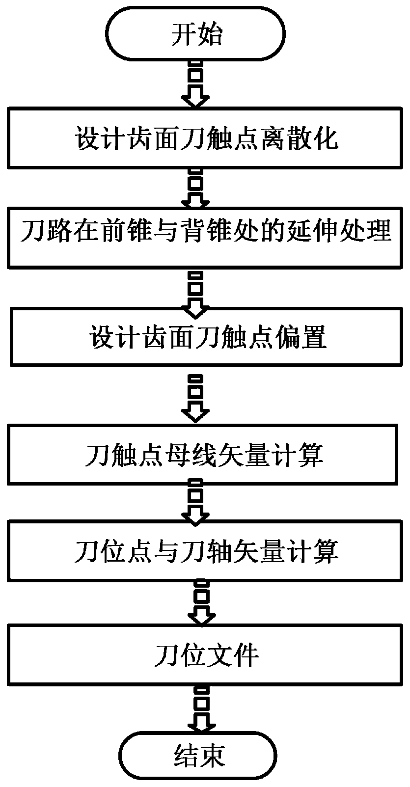
[0058] A machining method for side edge milling of spiral bevel gear tooth surface, such as figure 1 shown, including the following steps:

[0059] Step 1: The tooth surface of the gear design is uniformly discretized into a knife contact point cloud:

[0060] In the 3D CAD software, take the equivalent tool step length and tool path spacing to generate a uniform discretized tool contact point cloud on the tooth surface; and extract the tool contact coordinates of the spiral bevel gear design tooth surface (x n 、y n ,z n ) and the normal vector of the tooth surface at the knife contact point (u n , v n 、w n ).

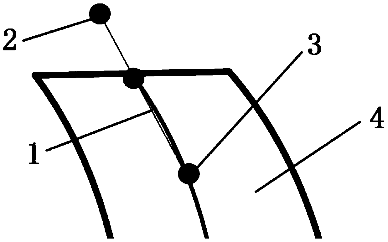
[0061] Step 2: The extension processing of the tool path at the front cone and the back cone:

[0062] Such as image 3 As shown in , the tool path is at the front cone and the back cone of the gear, which are the two ends of the tool path, and extension processing is required. The tool path extension adopts tangential straight line extension, and the extensio...


PUM


Abstract

The invention discloses a processing method for side edge milling of a spiral bevel gear tooth surface. The method comprises the following steps: step one, enabling a gear designed tooth surface to be uniformly discretized into a cutter contact point cloud; step two, extending a cutter path at a front cone and a back cone; step three, designing the cutter contact point cloud of the gear designed tooth surface to deviate at a working allowance along a tooth trench; step four, deducing a bus vector calculation formula of a taper end mill through the cutter contact; step five, deducing a calculation formula of coordinates of a cutter shaft vector and a cutter location point of a taper end mill; step six, calculating a cutter shaft vector and a cutter location point of each cutter contact of a spiral bevel gear tooth surface; and step seven, generating a cuter location file and completing the operation. Therefore, the cutter wearing uniformity is ensured; the service life of the cutter is prolonged; the surface quality of the tooth surface processing as well as the processing efficiency and stability of the part is improved.

Description

technical field [0001] The invention belongs to the technical field of CAM, and in particular relates to a processing method for flank milling of a spiral bevel gear tooth surface. Background technique [0002] Due to the complexity of the transmission principle of the spiral bevel gear, its traditional special machine structure and processing adjustment are the most complicated among all metal cutting machine tools and the processing cycle is long. With the development of computer technology and digital control technology, the realization of high-precision electronic transmission has opened up a new way for high-precision, high-efficiency and flexible gear processing. At present, foreign gear manufacturers have adopted advanced five-axis linkage CNC machining methods to process spiral bevel gears to improve their machining accuracy. Five-axis linkage CNC machining is widely used in the processing of complex parts such as molds, turbine blades, marine propellers and aviatio...

Claims


Application Information

Patent Timeline
Patent Type & Authority Applications(China)
IPC IPC(8): G05B19/4097
CPCG05B19/4097G05B2219/36141Y02P90/02
Inventor 张政吴海兵孙全平薛建勋许兆美陈小岗陈前亮王昆王硕
Owner HUAIYIN INSTITUTE OF TECHNOLOGY
Learn More