Back cavity gap circularly polarized millimeter wave antenna based on substrate integrated waveguide (SIW)

A substrate-integrated waveguide and millimeter-wave antenna technology, which is applied in slot antennas, antenna grounding switch structural connections, and radiating element structural forms, etc., can solve problems such as narrow axial specific bandwidth of millimeter-wave circularly polarized antennas, low antenna gain and efficiency, etc. problem, to achieve the effect of compact structure, high gain, and overcoming the complexity of the feeding structure

Pending Publication Date: 2019-09-20
XIDIAN UNIV
View PDF3 Cites 14 Cited by
  • Summary
  • Abstract
  • Description
  • Claims
  • Application Information

AI Technical Summary

Problems solved by technology

[0007] The purpose of the present invention is to overcome the deficiencies of the above-mentioned prior art, and propose a cavity-backed slot circularly polarized millimeter-wave antenna based

Method used


Image

  • Back cavity gap circularly polarized millimeter wave antenna based on substrate integrated waveguide (SIW)
  • Back cavity gap circularly polarized millimeter wave antenna based on substrate integrated waveguide (SIW)
  • Back cavity gap circularly polarized millimeter wave antenna based on substrate integrated waveguide (SIW)

Examples


Embodiment 1

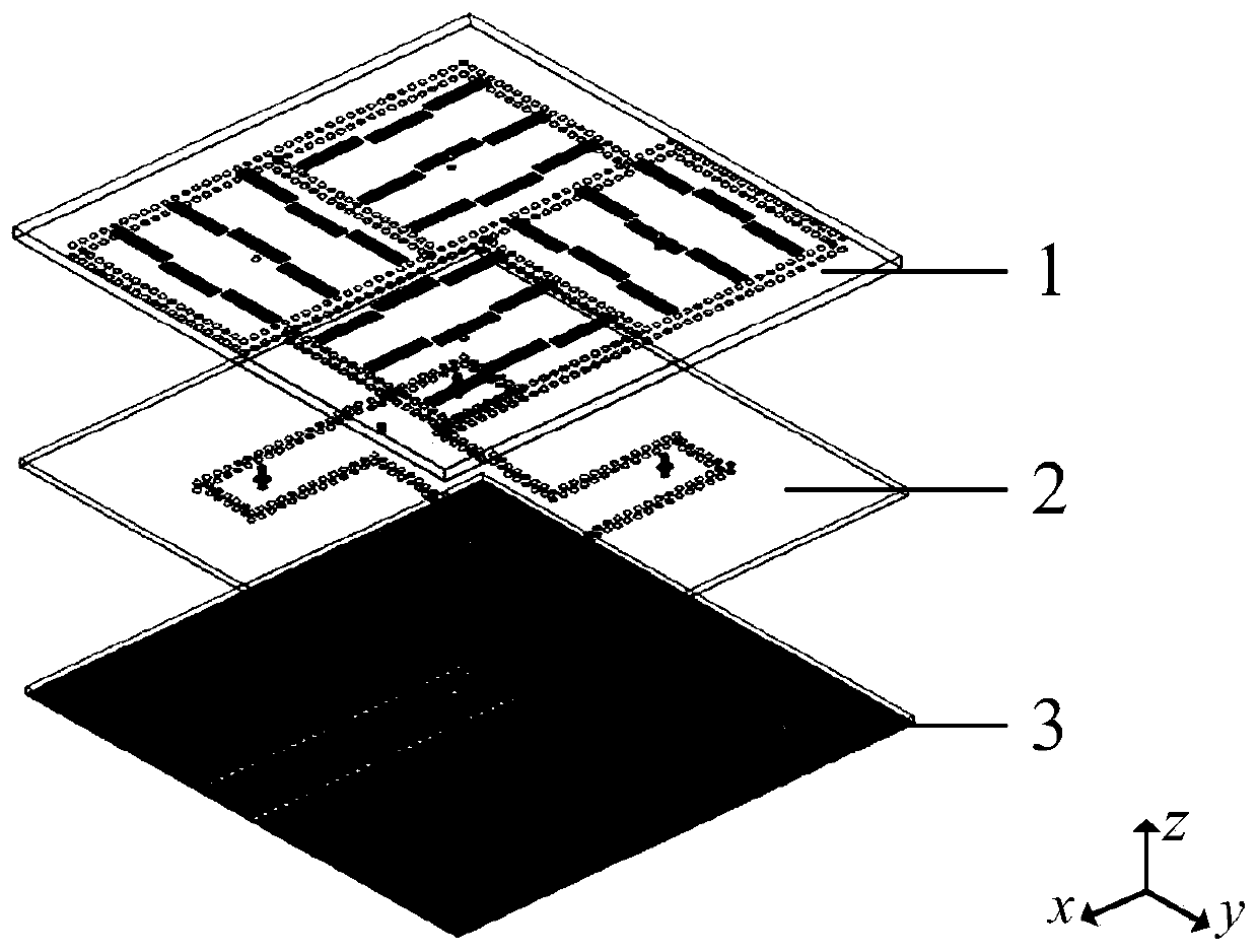
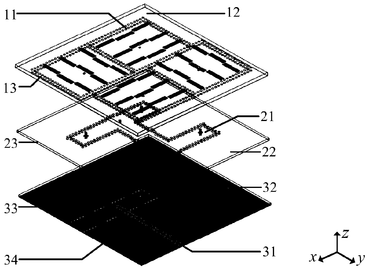
[0039] refer to figure 1 , figure 2 , image 3 , Figure 4 and Figure 5 , a cavity-backed slot circularly polarized millimeter-wave antenna based on a substrate-integrated waveguide SIW, its structure includes a radiation layer 1, a power layer 2, and a feed layer 3 from top to bottom, and the radiation layer 1 consists of four sequential The SIW square resonant cavity 11 arranged in rotation, the first metal patch 12 and the first rectangular dielectric plate 13 are composed; the power layer 2 is composed of a power divider 21, a second metal patch 22 and a second rectangular dielectric plate 23 composition; the feed layer 3 is composed of a rectangular SIW structure 31, a third metal patch 32, a third rectangular dielectric plate 33 and a fourth metal patch 34; the first metal patch 12, the second metal patch 22 are respectively covered on the upper surface of the first rectangular dielectric plate 13 and the second rectangular dielectric plate 23; the third metal patc...

Embodiment 2

[0053] The structure of this embodiment is the same as that of Embodiment 1, only the following parameters have been adjusted:

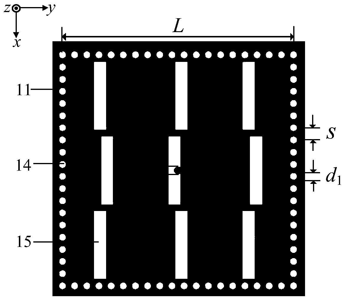
[0054] The side length L of the SIW square resonant cavity 11 is 15mm; the diameters of the first metal through hole 14, the second metal through hole 24 and the third metal through hole 35 are d 1 , where d 1 =0.45mm, and the distance between the centers of adjacent through holes is S=0.76mm; the length of the rectangular slit 15 is S L , the width is S W , where S L =4.46mm, S W =0.853mm; the diameter d of the through hole 16 2 =0.45mm; the length of the work-layered rectangular coupling gap 25 is L 1 , the width is W 1 , where L 1 =4.31mm, W 1 =0.2mm; the inner and outer diameters of the circular coupling slit 26 are respectively d 2 、d 3 , where d 2 = 0.45mm, d 3 =0.85mm; the diameter d of the circular impedance matching slit 27 4 =0.45mm; the distances between the circular impedance matching slit 27 and the two circular coupling sli...

Embodiment 3

[0056] The structure of this embodiment is the same as that of Embodiment 2, only the following parameters have been adjusted:

[0057] The side length L of the SIW square resonant cavity 11 is 15.4mm; the diameters of the first metal through hole 14, the second metal through hole 24 and the third metal through hole 35 are d 1 , where d 1 =0.55mm, and the distance between the centers of adjacent through holes is S=0.84mm; the length of the rectangular slit 15 is S L , the width is S W , where S L =4.56mm, S W =0.867mm; the diameter d of the through hole 16 2 =0.49mm; the length of the work-layered rectangular coupling gap 25 is L 1 , the width is W 1 , where L 1 =4.37mm, W 1 =0.24mm; the inner and outer diameters of the circular coupling slit 26 are respectively d 2 、d 3 , where d 2 = 0.49mm, d 3 =0.91mm; the diameter d of the circular impedance matching slit 27 4 =0.47mm; the distances between the circular impedance matching slit 27 and the two circular coupling ...


PUM


Abstract

Disclosed is a back cavity gap circularly polarized millimeter wave antenna based on substrate integrated waveguide (SIW). The back cavity gap circularly polarized millimeter wave antenna comprises a radiation layer, a power division layer and a feed layer; the radiation layer is composed of a SIW square resonant cavity, a first metal patch and a first rectangular dielectric plate; the power division layer is composed of a power divider, a second metal patch and a second rectangular dielectric plate; the feed layer is composed of a SIW structure, a third metal patch, a third rectangular dielectric plate and a fourth metal patch; the SIW square resonant cavity is provided with a first metal through hole, a rectangular gap is etched in the upper surface and a through hole is formed in the center in a run-through mode; the power divider is composed of a second metal through hole and probes, a power division layer rectangular coupling gap is etched in the center position, circular coupling gaps are formed in the periphery, and the probes penetrate through the respective circular coupling gaps; and the SIW structure is etched with a feed layer rectangular coupling gap and a feed layer metal through hole. The feed network transmission characteristic of the antenna is high, the gain in the working frequency band is high and the bandwidth is wide, and the antenna has the advantages of being simple in feeding structure, low in profile and compact in structure.

Description

technical field [0001] The invention belongs to the technical field of antennas, in particular to a cavity-backed slot circularly polarized millimeter-wave antenna based on a substrate integrated waveguide (SIW) in the field of cavity-backed slot antennas, which can be used in millimeter-wave wireless communication systems. Background technique [0002] With the rapid development of the mobile Internet and the Internet of Things, traditional mobile communication systems have been increasingly unable to meet people's needs, and the research and development of 5G mobile communication systems has been put on the agenda. The introduction of 5G has promoted the birth of many new technologies, among which millimeter wave technology is the most effective and innovative technology among many 5G technologies. Traditional mobile communication frequencies less than 3 GHz are increasingly crowded, while resources in the millimeter wave band are far from being developed. At the same tim...

Claims


Application Information

Patent Timeline
IPC IPC(8): H01Q13/18H01Q1/50H01Q1/38
CPCH01Q1/38H01Q1/50H01Q13/18
Inventor 洪涛杨博光赵哲民刘英姜文龚书喜
Owner XIDIAN UNIV
Why Eureka
Try Eureka