Cutter changing assembly structure and method for large-size microstructure array relay machining

A microstructure array and large-scale technology, applied in metal processing equipment, metal processing machinery parts, manufacturing tools, etc., can solve problems such as difficult calibration, inability to accurately locate new tools to the processing stop point, and inconsistent reference coordinate systems. achieve the effect of avoiding damage

Inactive Publication Date: 2019-09-24
ZHEJIANG UNIV
View PDF2 Cites 2 Cited by
  • Summary
  • Abstract
  • Description
  • Claims
  • Application Information

AI Technical Summary

Problems solved by technology

The key problem caused by the independence of the measuring instrument is that even if the position of the new tool and the position of the machining stop point can be accurately measured respectively, the coordinates of the two instruments are difficult to calibrate, which leads to the difference between the two positions relative to the reference coordinate system. Non-uniform, which prevents accurate positioning of the new tool to the machining stop

Method used


Image

  • Cutter changing assembly structure and method for large-size microstructure array relay machining
  • Cutter changing assembly structure and method for large-size microstructure array relay machining
  • Cutter changing assembly structure and method for large-size microstructure array relay machining

Examples


Embodiment 1

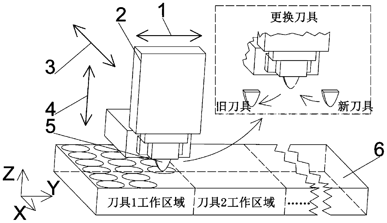
[0039] The schematic diagram of the tool change splicing structure of the first embodiment of the present invention is as follows: figure 1 Shown. Its main components are Y-direction slide 1 (including linear encoder), two-axis fast tool servo system with integrated force sensor 2, X-direction slide 3 (including linear encoder), Z-direction slide 4 (including linear encoder) 器), and replaceable tool 5, the figure also includes a large-size workpiece 6.

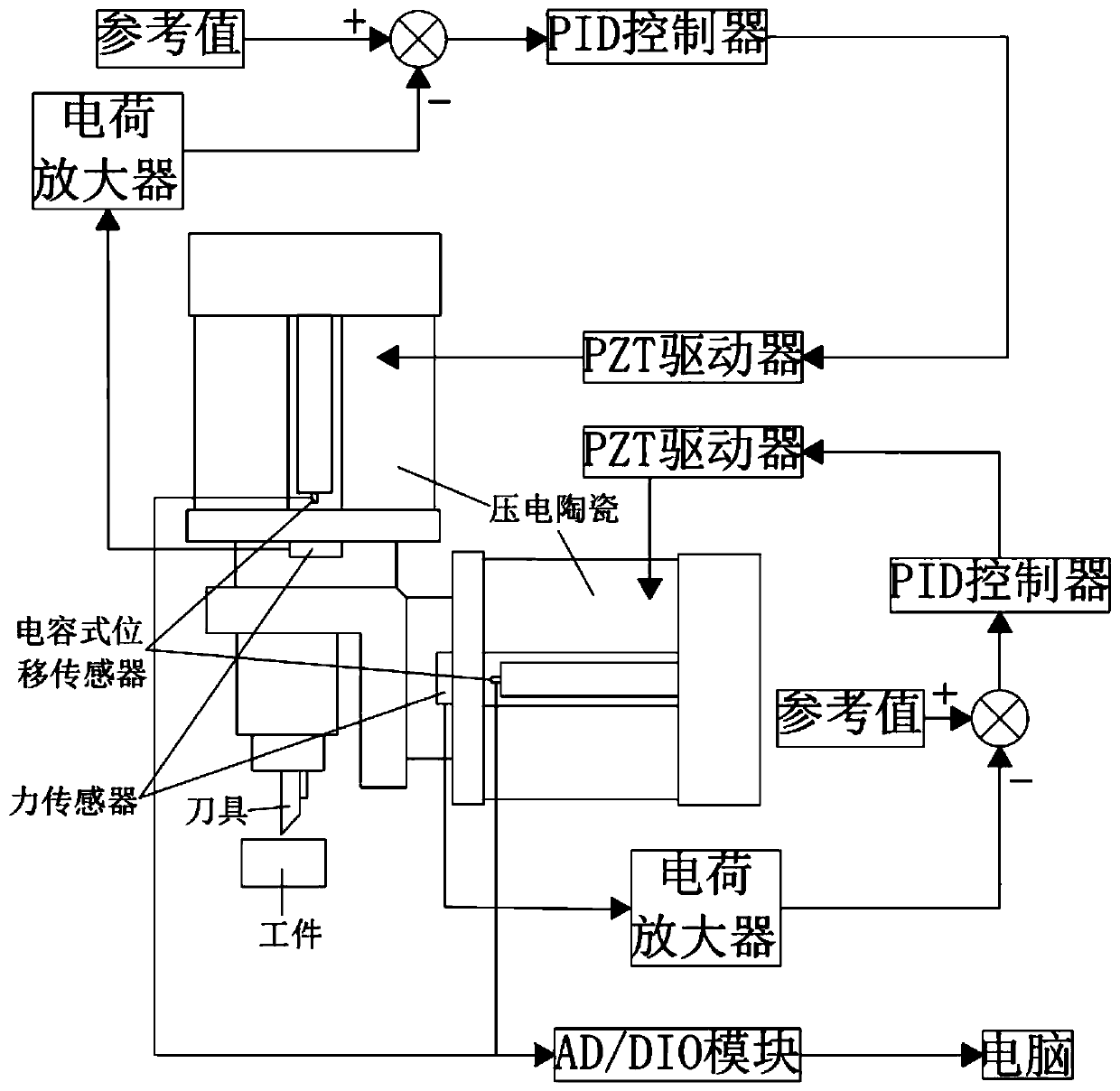
[0040] Also includes such as figure 2 In the control system shown, the two-axis fast tool servo system consists of a longitudinal fast tool servo and a horizontal fast tool servo. Servo control tool positioning adopts the method of force closed loop feedback control. The force sensor of the longitudinal fast tool servo detects the contact force between the tool and the workpiece in the longitudinal direction. After being amplified by the charge amplifier, it is compared with the reference signal as a feedback signal, and the comp...

Embodiment 2

[0044] The tool change splicing method of the second embodiment of the present invention includes the following steps:

[0045] 1) Detect the contact force between the tool and the workpiece in the longitudinal and transverse directions;

[0046] 2) Control the tool to perform displacement scanning along the topography of the processed microstructure on the surface of the workpiece, and at the same time, combine the reference signal to keep the magnitude of the longitudinal and lateral contact force constant through closed-loop control;

[0047] 3) Obtain the tool scanning path based on the tool displacement measured by the displacement sensor;

[0048] 4) Based on the acquired tool scan path, position the new tool to the processing stop point of the old tool.

[0049] Attached below figure 2 , 3 And 4(a)-(c) to explain in detail:

[0050] (1) In the process of splicing and changing tools, new tools are used to replace worn out tools. Such as image 3 As shown, suppose the position of...


PUM


Abstract

The invention provides a cutter changing assembly method for large-size microstructure array relay machining. The method comprises the following steps: (S1) the magnitudes of contact force between cutters and workpieces in both longitudinal and transverse directions are detected; (S2) the cutters are controlled for displacement scanning on the surfaces of the workpieces along morphologies of machined microstructures; and meanwhile, reference signals are combined for closed-loop control to maintain the magnitudes of the contact force in the longitudinal and transverse directions invariable; (S3) based on cutter displacements measured by displacement sensors, cutter scanning paths are obtained; and (S4) based on the obtained cutter scanning paths, new cutters are positioned in machining stop points of old cutters. The method directly uses the cutters as scanning probes, integrates a measuring function on the basis of a machining function, and finishes a positioning function by using a machining system to prevent the problem of difficult calibration of coordinates caused by mutual independence of a machining instrument and a measuring instrument.

Description

Technical field [0001] The invention relates to the technical field of mechanical processing, in particular to a self-positioning tool change splicing structure. Background technique [0002] The size and function of ultra-precision devices are constantly developing to extremes, such as large-size optical lenses, large flat panels, large photovoltaic power generation panels, etc. The overall size can reach several m^2 or even tens of m^2, while the size requirements of the surface microstructure Reaching the order of sub-micron, so large-size ultra-precision device processing is a macro / micro / nano cross-scale manufacturing process. In order to mass produce large-size ultra-precision devices, it is necessary to use molds for mass imprinting, and ultra-precision machining based on single-point diamond tool cutting is an effective method for manufacturing large-size ultra-precision molds. The fast tool servo mechanism is a typical representative of single-point diamond tool cutting...

Claims


Application Information

Patent Timeline
Patent Type & Authority Applications(China)
IPC IPC(8): B23Q17/22B23Q17/00
CPCB23Q17/00B23Q17/2241
Inventor 陈远流陈甫文
Owner ZHEJIANG UNIV
Why Eureka
Try Eureka