
A new device and method for rapid and continuous generation of hydrates on trays
A technology of hydrates and trays, applied in feeding devices, chemical instruments and methods, chemical/physical processes, etc., can solve problems such as storage difficulties, slow hydrate formation steps, and limited gas-liquid interface mass transfer, etc., to achieve Enhanced self-cleaning ability, stable impact-resistant mechanical properties, and reasonable device structure design
- Summary
- Abstract
- Description
- Claims
- Application Information
AI Technical Summary
Problems solved by technology
Method used
Image

Examples
Embodiment 1
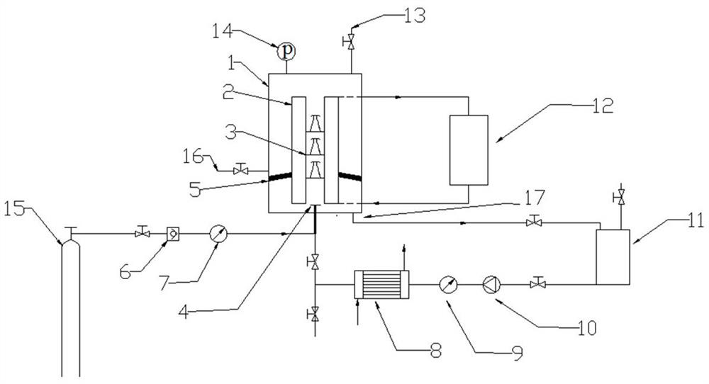
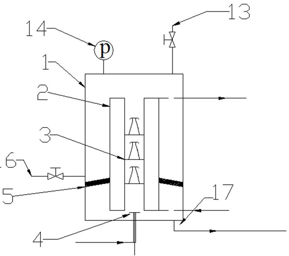
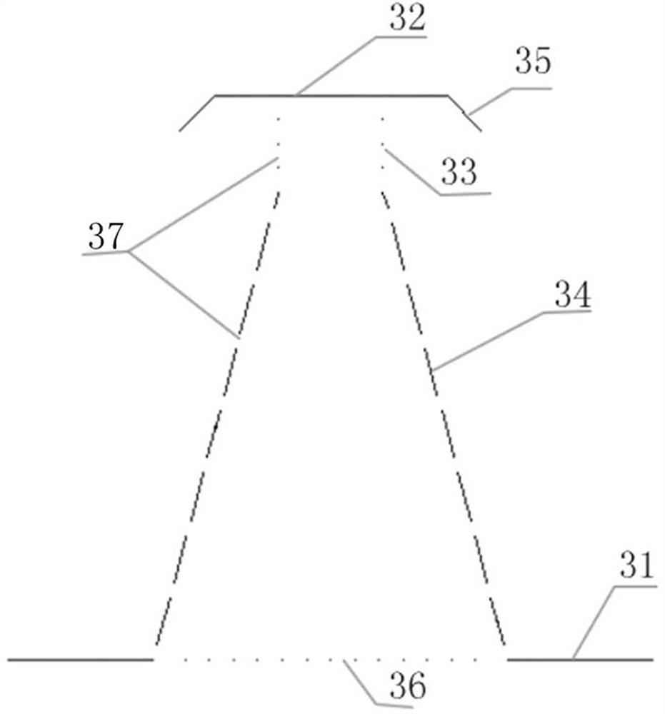
[0030] Such as figure 1 , figure 2 , image 3 and Figure 4 A new type of rapid and continuous hydrate generation device with trays is shown, including a reactor, the reactor includes an inner cylinder 2 and an outer cylinder 1, the inner cylinder 2 is the hydrate formation zone, and the outer cylinder 1 zone is the hydrate Aggregation and separation areas. A circulating cooling device 12 is arranged outside the inner cylinder 2, a sieve plate 5 is installed between the inner cylinder 2 and the outer cylinder 1 inclined toward the outer cylinder 1, and a circulating water outlet and a discharge port 16 are arranged at the bottom of the outer cylinder 1, and the discharge port 16 is located on the sieve plate 5 above.
[0031] An inner jacket is arranged on the outer side of the 2 walls of the inner cylinder, and the inner jacket is equipped with a circulating cooling liquid. The circulating cooling liquid inlet and the circulating cooling liquid outlet of the inner jacket...
PUM
 Abstract
Description
Claims
Application Information