Bluetooth technology based automobile high beam and low beam automatic control system
A technology of automatic control system, far and near light, applied in optical signals, vehicle parts, signal devices, etc.
- Summary
- Abstract
- Description
- Claims
- Application Information
AI Technical Summary
Problems solved by technology
Method used
Image
Examples
Embodiment 1
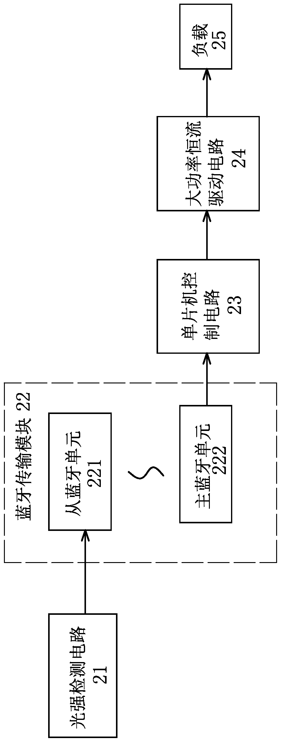
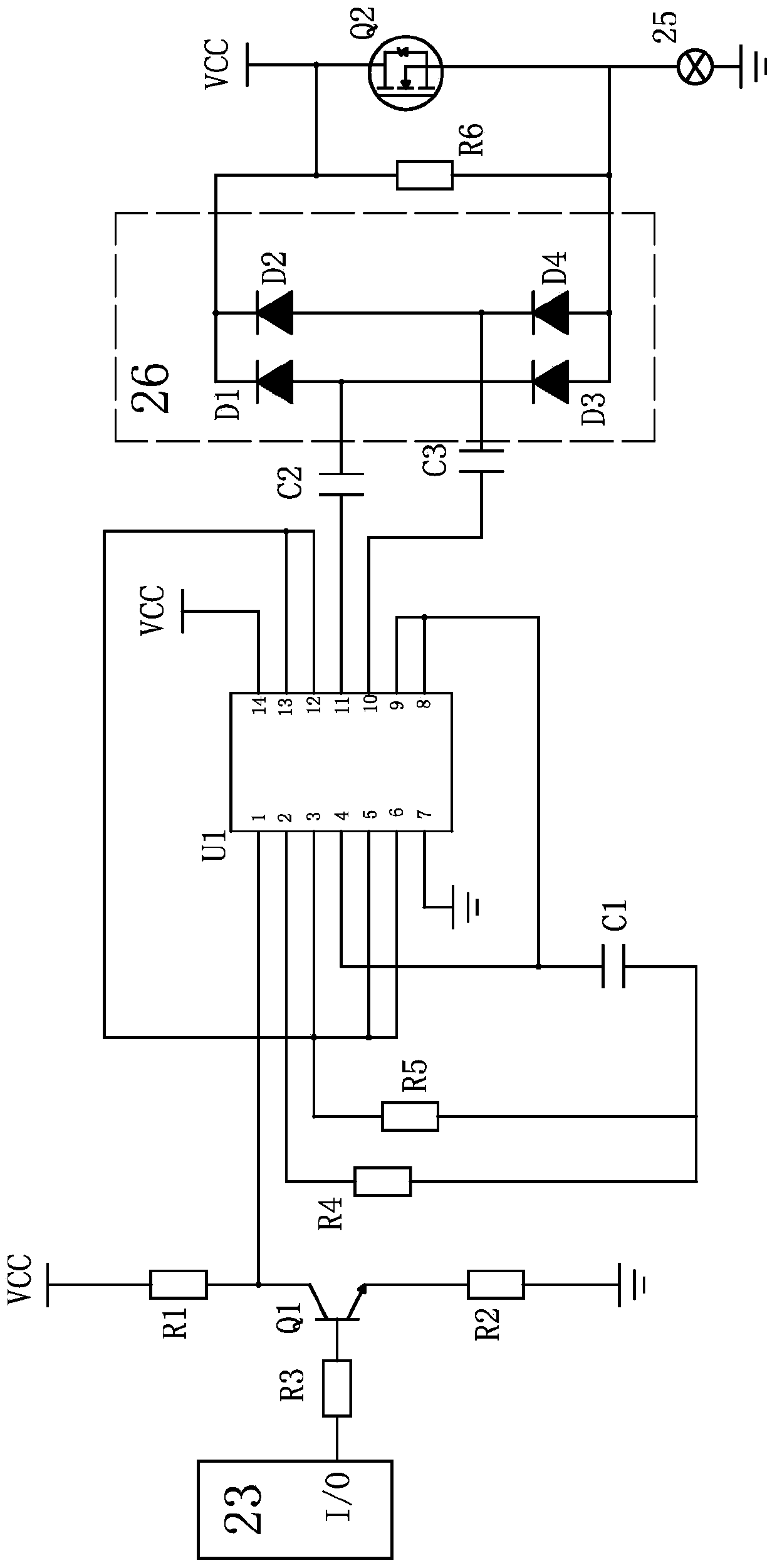
[0029] Embodiment one, such as figure 1 , 3 As shown, the automatic control system for high and low beams of automobiles based on bluetooth technology includes a single-chip microcomputer control circuit 23 and a load 25, a light intensity detection circuit 21 arranged in the cab for detecting the light intensity of the cab, and a light intensity detection circuit for transmission of light intensity detection data. The bluetooth transmission module 22 and the high-power constant-current drive circuit 24 for driving the load 25 work, the light intensity detection circuit 21, the bluetooth transmission module 22, the single-chip microcomputer control circuit 23 and the high-power constant-current drive circuit 24 are connected in sequence, and the high-power constant The flow driving circuit 24 includes a MOS tube Q2, and the single-chip microcomputer control circuit 23 controls the conduction and cut-off of the MOS tube Q2 to realize the switching of the working state of the lo...
Embodiment 2
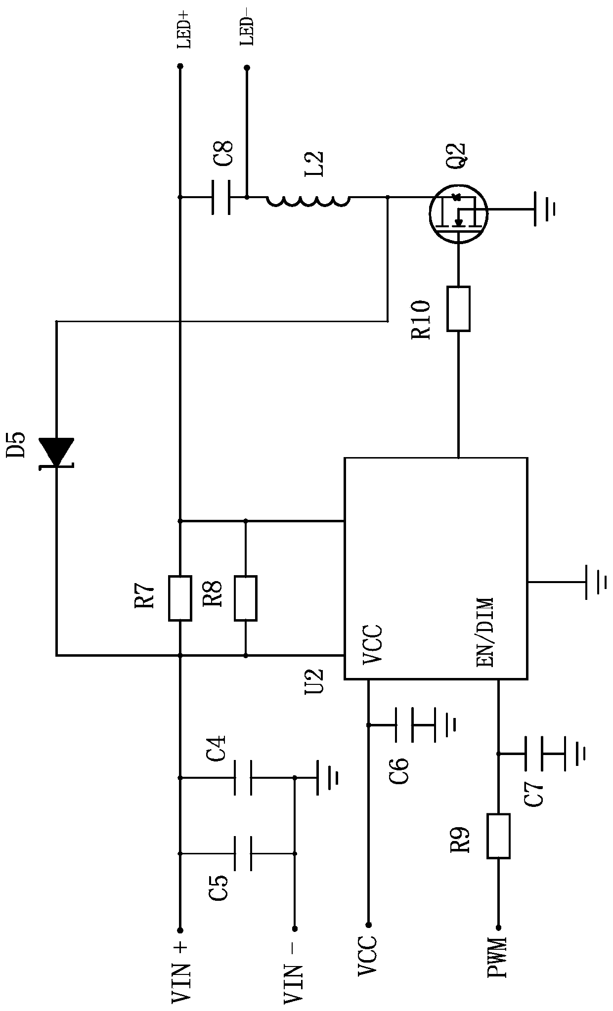
[0037] Embodiment two, such as figure 2 As shown, the high-power constant-current driving circuit 24 also includes a step-down driving integrated chip U2, a resistor R7, a resistor R9, a resistor R10, a capacitor C4, a capacitor C5, a capacitor C6, a capacitor C7, a Zener diode D5, and an inductor L2. Terminals are connected in parallel with capacitor C4 and capacitor C5, and then resistor R7 is connected in series. The output terminal of resistor R7 is connected to the positive pole of load 25. The positive and negative poles of load 25 are also connected in parallel with capacitor C8. Capacitor C8 is connected to the drain of MOS transistor Q2 through inductor L2. , the drain of the MOS transistor Q2 is also forwardly connected to the positive pole of the power supply through the regulator diode D5, the resistor R7 is also connected in parallel with the resistor R8, the output terminal of the resistor R8 is connected to the negative pole of the load 25, and the step-down dri...
PUM
 Abstract
Description
Claims
Application Information
 - R&D
- Intellectual Property
- Life Sciences
- Materials
- Tech Scout
- Unparalleled Data Quality
- Higher Quality Content
- 60% Fewer Hallucinations
Browse by: Latest US Patents, China's latest patents, Technical Efficacy Thesaurus, Application Domain, Technology Topic, Popular Technical Reports.
© 2025 PatSnap. All rights reserved.Legal|Privacy policy|Modern Slavery Act Transparency Statement|Sitemap|About US| Contact US: help@patsnap.com


