Pneumatic control valve and gas-liquid pressure conversion control device

A technology of pneumatic control valve and air valve, which is applied in the direction of fluid pressure actuating device, accumulator device, mechanical equipment, etc., can solve the problems of large inner plate space of machine tool, enlarged oil tank volume, unstable oil supply pressure, etc. , to achieve the effect of simplifying the machine tool application circuit, simplifying the hydraulic system, and improving work efficiency

Active Publication Date: 2019-09-27
NANJING BLESSED HYDRAULIC MACHINERY
View PDF10 Cites 7 Cited by
  • Summary
  • Abstract
  • Description
  • Claims
  • Application Information

AI Technical Summary

Problems solved by technology

The advantage of this oil supply method is that the oil supply pressure is stable, the oil supply pulsation is small, and the noise is small, but the disadvantages of this oil supply method are also obvious, mainly in the following aspects: First, the oil pump motor unit occupies the upper cover of the oil tank. The space is larger; second, the weight of the oil pump motor unit is relatively large; third, the energy consumption of the oil pump motor unit is relatively large, especially when the hydraulic system needs to maintain pressure, the oil pump needs to continuously provide high-pressure oil to the chuck. To maintain the clamping of the chuck, the motor must run at full speed all the time, this part of energy is wasted, although most hydraulic stations now
[0003] The automatic variable pump is selected to reduce the energy consumption of the system to a certain extent, but the hydraulic system still needs to consume a lot of power when it is always running under high pressure, and the efficiency of the motor under light load is also low
Large energy consumption also makes the oil temperature of the hydraulic system easy to rise, so that the hydraulic system has to take auxiliary measures such as increasing the volume of the oil tank and adding an air cooler or water cooler to help the hydraulic system dissipate heat, which increases the size of the hydraulic system and occupies There is a lot of space in the inner panel of the machine tool, and the heat dissipation design of the hydraulic system needs to be considered in the machine tool, which increases the workload of the machine tool design
At present, the gas-liquid booster device can solve the energy consumption problem of the hydraulic system. The gas-liquid booster device is driven by the reciprocating action of the cylinder to provide the high-pressure oil required for the operation of the machine tool. It is enough to maintain a certain pressure in the cylinder, and the cylinder does not move. At this time, the energy consumption of the hydraulic system is extremely small, the system does not generate heat, and no heat dissipation device is required, so the size of the hydraulic system can be greatly reduced, but the current gas-liquid pressurization Due to the reciprocating motion of the cylinder to absorb and discharge oil, the device has the disadvantages of unstable oil supply pressure and large oil supply pulsation

Method used


Image

  • Pneumatic control valve and gas-liquid pressure conversion control device
  • Pneumatic control valve and gas-liquid pressure conversion control device
  • Pneumatic control valve and gas-liquid pressure conversion control device

Examples


Embodiment Construction

[0016] In order to describe the technical solutions disclosed in the present invention in detail, further elaboration will be given below in conjunction with specific embodiments and accompanying drawings.

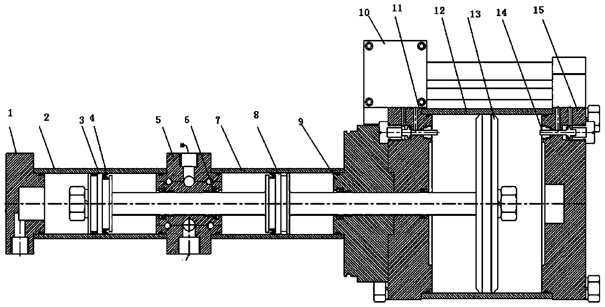
[0017] Aiming at the defects of traditional gas-liquid control devices or gas-liquid booster devices, the present invention provides a gas-hydraulic pressure conversion control device, which uses a combination of a large-diameter cylinder and a small-diameter hydraulic cylinder, and uses the push-pull reciprocating motion of the cylinder to drive The piston of the hydraulic cylinder reciprocates to complete the oil suction and oil discharge functions of the gas-hydraulic booster. The gas-liquid conversion control device uses a double-acting cylinder to drive two hydraulic cylinders connected in series through a piston rod. The pistons of the cylinder and the hydraulic cylinder are rigidly connected. Whether it is forward or backward, the two actions of oil suction and oil ...


PUM


Abstract

The invention discloses a pneumatic control valve and a gas-liquid pressure conversion control device. The gas-liquid pressure conversion control device drives two oil cylinders to alternately act through one air cylinder and implements oil suction and oil outlet simultaneously. The gas-liquid pressure conversion control device controls air intake through the pneumatic control valve to push a piston rod to move and controls the oil cylinders to output oil alternately to provide pressure. The oil outlet pressure of a hydraulic cylinder composed of the oil cylinders is controlled through the pneumatic control valve to regulate the air intake pressure. A hydraulic energy accumulator buffers pressure pulsation, caused discontinuous oil supply occurring at the reversing moment of the air cylinder, of the gas-liquid boosting control device. Moving components such as a piston of the gas-liquid pressure conversion control device are made of aluminum alloy materials. The weight of reciprocating motion components is reduced as far as possible while the strength is ensured, the reversing sensitivity is improved, and energy consumption and pressure pulsation are both reduced.

Description

technical field [0001] The invention belongs to gas-liquid conversion equipment, in particular to a pneumatic control valve and a gas-liquid pressure conversion control device. Background technique [0002] At present, the hydraulic systems of CNC machine tools basically use electric motors to drive hydraulic pumps to provide chucks, tailstocks, and high-pressure oil required for the operation of tool holders to drive them to operate. The advantage of this oil supply method is that the oil supply pressure is stable, the oil supply pulsation is small, and the noise is small, but the disadvantages of this oil supply method are also obvious, mainly in the following aspects: First, the oil pump motor unit occupies the upper cover of the oil tank. The space is larger; second, the weight of the oil pump motor unit is relatively large; third, the energy consumption of the oil pump motor unit is relatively large, especially when the hydraulic system needs to maintain pressure, the o...

Claims


Application Information

Patent Timeline
Patent Type & Authority Applications(China)
IPC IPC(8): F15B15/08F15B15/20F15B1/02
CPCF15B1/021F15B15/08F15B15/202
Inventor 陈海楼成才飞
Owner NANJING BLESSED HYDRAULIC MACHINERY
Why Eureka
Try Eureka