
Machining Method of Drive Gear Hole System for Medium Speed ​​Diesel Engine Frame

A technology of transmission gears and processing methods, applied in metal processing equipment, manufacturing tools, boring/drilling and other directions, can solve the problems of large accumulative errors in clamping and alignment, inability to ensure positioning dimensional accuracy, and unstable processing quality. , to achieve the effect of high work efficiency, avoiding errors and short auxiliary time

Active Publication Date: 2020-05-12
CSSC MARINE POWER
View PDF14 Cites 0 Cited by
  • Summary
  • Abstract
  • Description
  • Claims
  • Application Information

AI Technical Summary

Problems solved by technology

The traditional transmission gear hole system is processed by a CNC horizontal boring and milling machine. During processing, multiple clamping and positioning are required, and multiple stations need to find out the benchmarks several times to complete. Not only the auxiliary time is long, the work efficiency is low, and the labor intensity is high. Moreover, the accumulative errors of clamping and alignment are large, and the errors generated in the processing process often cannot guarantee the positioning and dimensional accuracy of each hole, and the processing quality of the product is extremely unstable.

Method used


Image

  • Machining Method of Drive Gear Hole System for Medium Speed ​​Diesel Engine Frame
  • Machining Method of Drive Gear Hole System for Medium Speed ​​Diesel Engine Frame
  • Machining Method of Drive Gear Hole System for Medium Speed ​​Diesel Engine Frame

Examples


Embodiment Construction

[0021] The present invention will be further described below in conjunction with drawings and embodiments.

[0022] The processing method of the transmission gear hole system of the medium-speed diesel engine frame includes the following steps:

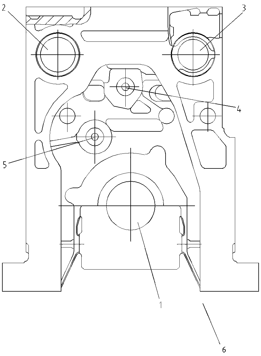
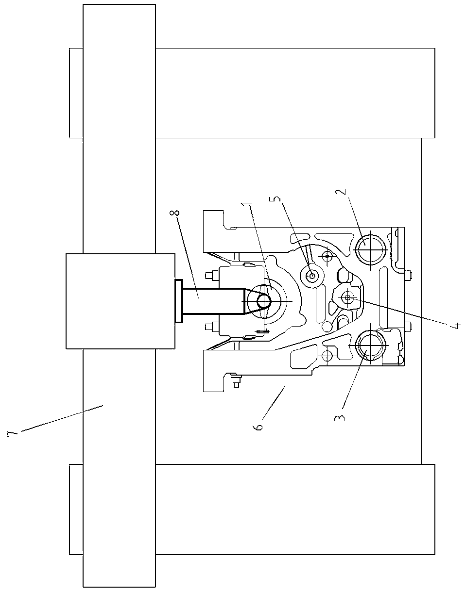
[0023] 1) Machining the main bearing hole 1: such as figure 2 As shown, put the bottom of the diesel engine frame 6 upwards, clamp and position it on the workbench of the CNC gantry boring and milling machine 7, and make the axis of the main bearing hole 1 on the frame 6 perpendicular to the axis of the machine tool spindle, and install it on the machine tool spindle The first special attachment 8 starts the machine tool, and utilizes the first special attachment 8 to process the main bearing holes 1 of each gear in turn. During processing, the axis of the first special attachment 8 coincides with the axis of the main bearing holes 1 of each gear respectively;

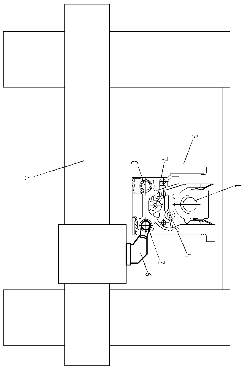
[0024] 2) Processing oil injection camshaft hole 2: such as image 3 A...


PUM


Abstract

The invention discloses a medium-speed diesel engine frame transmission gear hole system machining method. The method comprises the following steps that (1) the bottom face of a diesel engine frame ismade to face upwards, and all gears of main bearing holes are machined through a first special accessory; (2) the top face of the diesel engine frame is made to face upwards, and all gears of oil injection camshaft holes are machined through a second special accessory; (3) all gears of air exhaust cam shaft holes are machined through the second special accessory; (4) actual position coordinates of the oil injection camshaft holes and the air exhaust cam shaft holes are found through a third special accessory, the coordinate value of a transition gear is worked out, and a transition gear holeis machined through the third special accessory; and (5) the transition gear hole and the main bearing holes serve as the criterion, the coordinate value of an intermediate gear hole is worked out, and the intermediate gear hole is machined through the third special accessory. According to the medium-speed diesel engine frame transmission gear hole system machining method, the auxiliary time is short, the working efficiency is high, the labor intensity is low, in addition, the accumulative error of clamping and aligning is small, the machining error is small, the positioning dimension precision between the holes is ensured, and accordingly, the product machining quality is ensured.

Description

technical field [0001] The invention relates to a numerical control machining method for a medium-speed diesel engine frame, in particular to a machining method for a transmission gear hole system on a medium-speed diesel engine frame, and belongs to the technical field of numerical control machining. Background technique [0002] The processing of transmission gear hole system of marine medium-speed diesel engine frame is one of the key points and difficulties in frame processing. The transmission gear hole system is mainly used to install the transmission gear set. The crankshaft drives the transmission gear set. The transmission gear set drives the exhaust camshaft and the fuel injection camshaft to work. The backlash of the transmission gear set is different from that of the crankshaft gear and the camshaft gear. The positioning dimensions of each hole are related to each other, so the position and dimension accuracy of the transmission gear hole system is very high, whi...

Claims


Application Information

Patent Timeline
Patent Type & Authority Patents(China)
IPC IPC(8): B23B35/00B23B41/00
CPCB23B35/00B23B41/00
Inventor 徐希方廖新山朱俊伟段真奇王静苏揆
Owner CSSC MARINE POWER
Learn More