High-power traction auxiliary converter

A technology for auxiliary converters and traction converters, applied in the field of converters, can solve the problems of large size, large installation space, inconvenient maintenance and other problems, and achieve simple and efficient assembly and production, high integration, and reduced The effect of small electrical disturbances

Active Publication Date: 2019-10-01
XIAN YONGDIAN ELECTRIC
View PDF7 Cites 10 Cited by
  • Summary
  • Abstract
  • Description
  • Claims
  • Application Information

AI Technical Summary

Problems solved by technology

[0003] Most of the existing electric locomotive converters are less than three sets of traction converters or traction auxiliary converters with low power. These converters are not highly integrated and have low power density. Large size, resulting in a large footprint, and the problem that the power density cannot be increased
[0004] In order to realize the control function

Method used


Image

  • High-power traction auxiliary converter
  • High-power traction auxiliary converter
  • High-power traction auxiliary converter

Examples


Embodiment 1

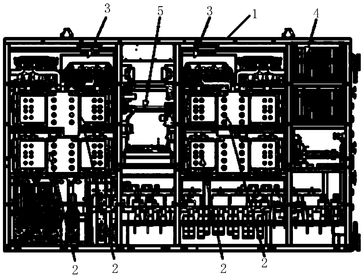
[0033] see figure 1 As shown, the high-power traction auxiliary converter provided by the present invention includes: a cabinet body 1, and four sets of traction converters 2, two sets of auxiliary converters 3, a control unit 4 and a cooling unit 5 are arranged in the cabinet body 1 Two sets of traction converters 2 and one set of auxiliary converters 3 are arranged on both sides of the cooling unit 5; the control unit 4 is located on the upper right of the cabinet body 1, and the cooling unit 5 controls the traction converters 2 and auxiliary converters at the same time. flow device 3 for cooling.

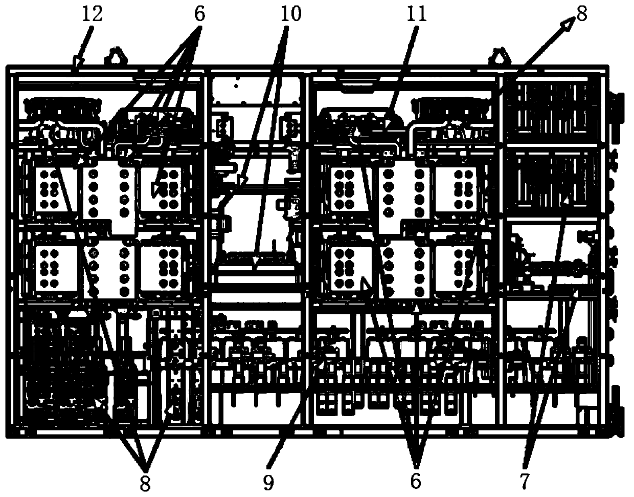
[0034] Further, the cabinet includes power modules and capacitor components 6, low-voltage electrical components 7, switch electrical components 8, sensor components 9, cooling components 10, copper bar components 11, box components 12, and low-voltage line components. High voltage auxiliary components and door components.

[0035] Further, the power module and capacitor assemb...

Embodiment 2

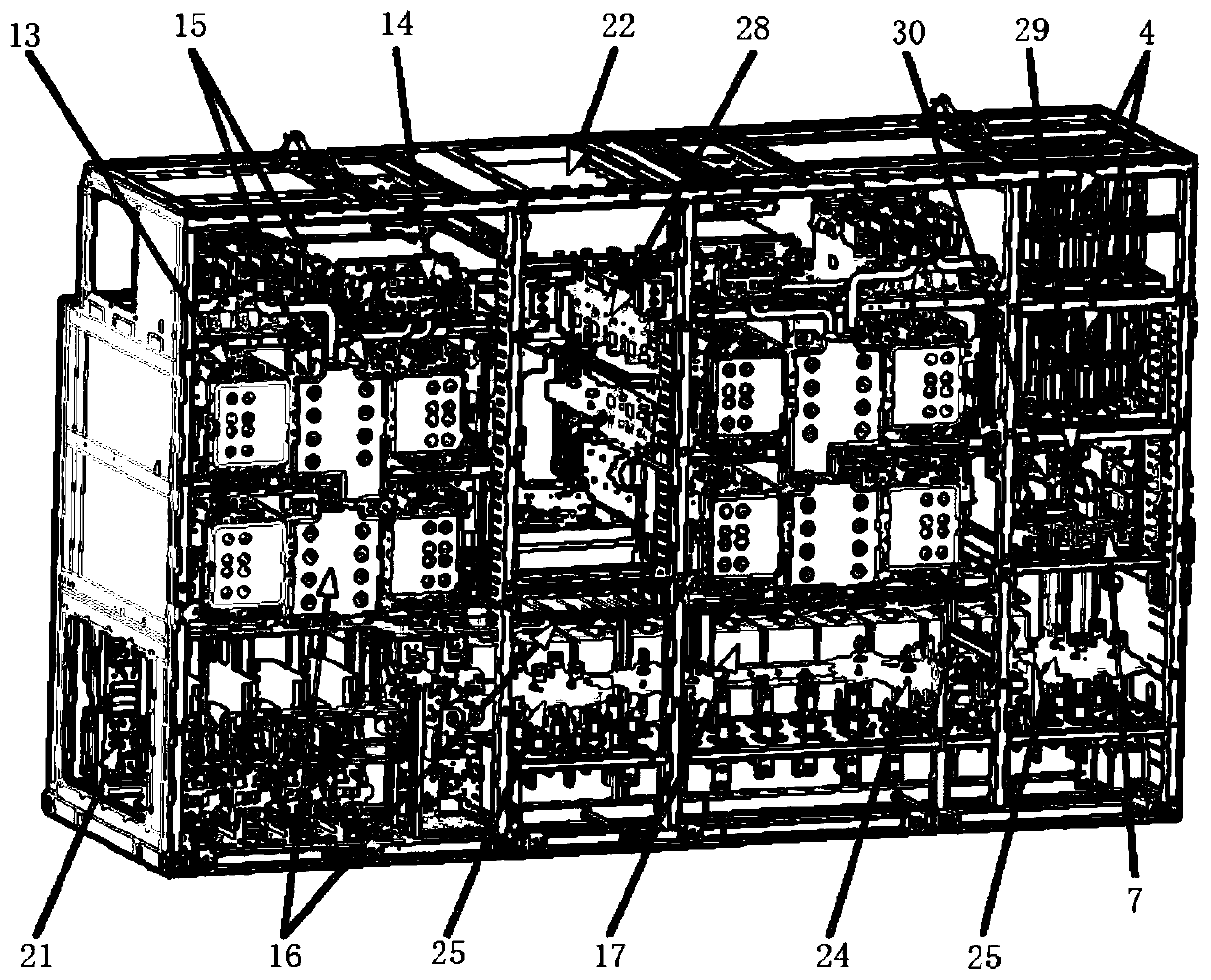
[0054] The present invention also provides a high-power traction auxiliary converter, see figure 1 As shown, it mainly includes ten kinds of components, see Figure 2-3 As shown, the power module and capacitor assembly 6 (including traction power module 13, auxiliary inverter power module 14, intermediate support capacitor 15, secondary filter capacitor 17, composite busbar 16 and other main components), low-voltage Control unit, relay, voltage transformer, current transformer, filter and other main components), switching electrical components 8 (mainly including main contactor 18, pre-charging contactor 20, isolating switch 19, pre-charging resistor 21, chronic discharge resistor , chopper resistance 22 and other main components), sensor assembly 9 (including current sensor and voltage sensor 28, pressure sensor 29, temperature sensor 30, etc. of input and output ground loops and intermediate loops), cooling assembly 10 (including temperature control device 33 , resistance w...


PUM

PropertyMeasurementUnit
Thicknessaaaaaaaaaa
Thicknessaaaaaaaaaa

Abstract

The invention belongs to the technical field of converters, and relates to a high-power traction auxiliary converter. The high-power traction auxiliary converter includes a cabinet body which is internally equipped with four traction converters, two auxiliary converters, a control unit and a cooling unit. Two traction converters and one auxiliary converter are arranged on each of the two sides ofthe cooling unit. The control unit is located at the upper right of the cabinet body. The cooling unit cools the traction converters and the auxiliary converters at the same time. The four traction converters and the two auxiliary converters are integrated and used on the power centralized electric multiple units of a certain electric locomotive company to provide a suitable power supply for locomotive traction motors and auxiliary loads. The converter adopts a modular and symmetrical design, is small, light, sealed, highly redundant and highly integrated. The converter is simple and efficientin assembly and production, and can meet the design requirement for a lightweight and highly integrated whole locomotive. The structure space is greatly saved, the degree of integration is improved,and electrical interference is reduced.

Description

technical field [0001] The invention belongs to the technical field of converters, and relates to a traction auxiliary converter, in particular to a high-power traction auxiliary converter. Background technique [0002] The traction auxiliary converter is an important part of the AC drive electric locomotive. Its function is to realize the conversion of the AC power in the power frequency grid into AC power suitable for the operation requirements of the AC motor and variable frequency through frequency conversion and voltage conversion control, and complete the electric locomotive. traction / braking performance, and the performance of power supply to auxiliary loads. Its electrical design and cabinet layout design are related to the performance realization and stability of the entire transmission system. [0003] Most of the existing electric locomotive converters are less than three sets of traction converters or traction auxiliary converters with low power. These converter...

Claims


Application Information

Patent Timeline
IPC IPC(8): H02M5/00H05K7/14H05K7/20
CPCH02M5/00H05K7/1432H05K7/20927
Inventor 裴冰赵娜李秋玲王雷田尚川
Owner XIAN YONGDIAN ELECTRIC
Why Eureka
Try Eureka