Jet aeration arm and integrated jet aerator containing jet aeration arms

A jet aeration and aeration technology, applied in the field of water treatment, can solve the problems of low mass transfer efficiency and power efficiency, limited gas-liquid two-phase contact area, and low oxygen mass transfer efficiency, so as to improve the efficiency of sewage treatment, Improve mass transfer efficiency and power efficiency, and enhance the effect of turbulence

Pending Publication Date: 2019-10-08
WELLE ENVIRONMENTAL GRP CO LTD
View PDF0 Cites 3 Cited by
  • Summary
  • Abstract
  • Description
  • Claims
  • Application Information

AI Technical Summary

Problems solved by technology

However, the outlet diameter of the current aeration arm is the same as that of the mixing chamber, and the diameter of the first-stage nozzle is the same as that of the liquid phase inlet, and there is no gradient change, which makes the gas-liquid two-phase mixing area have no pressure change, to a certain extent affects the mass transfer efficiency of oxygen in the liquid phase
Secondly, the air inlet of the aeration arm is a circular hole air intake structure, the gas phase mass transfer in the mixing chamber is only carried out on the gas-liquid two-phase surface, and the mass transfer efficiency of oxygen is low
Furthermore, there are no components installed in the mixing chamber of the aeration arm, the gas-liquid two-phase contact area in the chamber is limited, and the degree of turbulence is weak. Therefore, the existing integrated jet aerator has oxygen mass transfer in the liquid phase. The efficiency and power efficiency are not high, and the problem of high energy consumption

Method used


Image

  • Jet aeration arm and integrated jet aerator containing jet aeration arms
  • Jet aeration arm and integrated jet aerator containing jet aeration arms
  • Jet aeration arm and integrated jet aerator containing jet aeration arms

Examples


Embodiment Construction

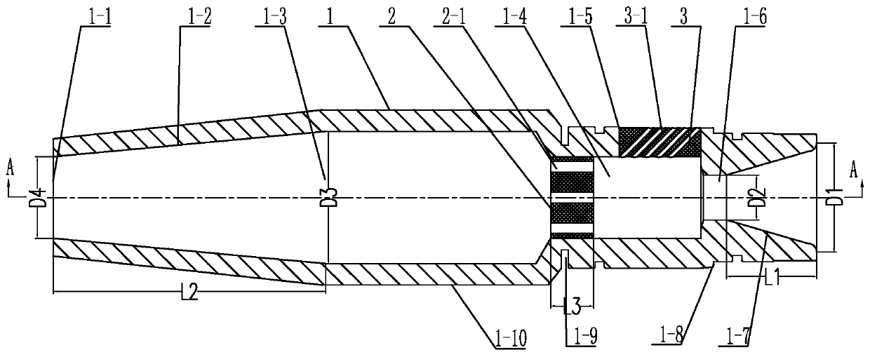
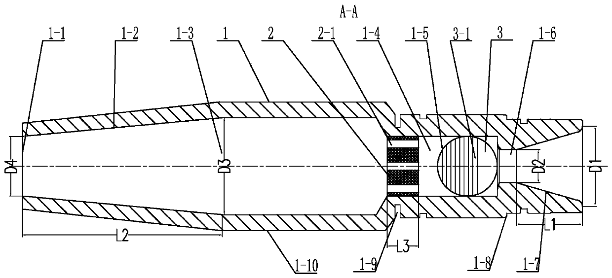
[0015] See figure 1 , 2 As shown, the jet aeration arm of the present invention includes an arm body 1-10 with a cavity inside, and the rear portion of the arm body 1-10 has a water inlet hole 1-7 and an arm body 1-10 for passing into the liquid phase. The 10 sides are used to pass into the air inlet 1-5 of the gas phase, and the arm body 1-10 cavity is provided with a primary nozzle 1-6 between the water inlet 1-7 and the air inlet 1-5, and the water inlet 1-7 has a first tapering part and transitions to a first-stage nozzle 1-6, and the ratio of the axial length to the diameter difference of the first tapering part of the water inlet hole 1-7 is 0.8 to 1.6, that is, the water inlet hole 1-7 The axial length L1 / major diameter D1-minor diameter D2, the axial length and diameter difference ratio of the first tapering part can also be 1.0-1.4, because the liquid phase can make the aperture of the water inlet hole 1-7 gradually along the flow direction Decrease, so that the pre...


PUM


Abstract

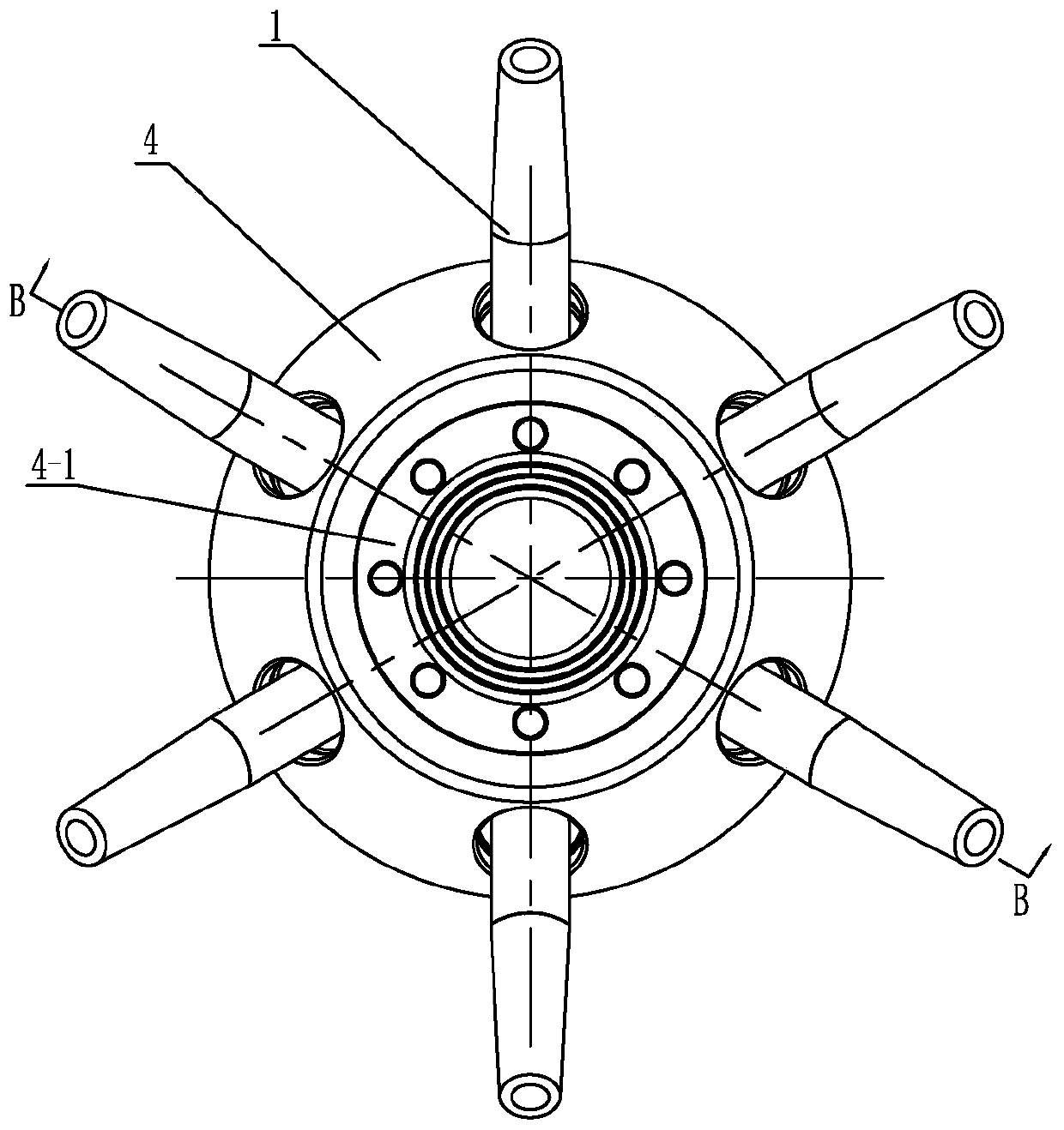
The invention relates to a jet aeration arm and an integrated jet aerator containing the jet aeration arms. The rear of an arm body of the jet aeration arm is provided with a water inlet hole and an air inlet hole, the inside of an hollow cavity of the arm body, between the water inlet hole and the air inlet hole, is provided with a first-stage nozzle, the water inlet hole is provided with a firsttapered portion transitioning to the first-stage nozzle, a partition plate with a plurality of oblique air passages is arranged at the air inlet hole of the arm body, outlets of the oblique air passages face a screen mesh hole plate, the inside of the hollow cavity of the arm body, at the front of the air inlet hole, is provided with the screen mesh hole plate, the screen mesh hole plate dividesthe hollow cavity of the arm body into a mixing cavity for gas-liquid mixing and a mixing cutting cavity for gas-liquid mixing cutting, a plurality of gas-liquid flow channels on the screen mesh holeplate communicate the mixing cavity with the mixing cutting cavity, and the mixing cavity of the arm body passes through a second tapered portion to a front second-stage nozzle. According to the jet aeration arm and the integrated jet aerator, the turbulence degree of gas-liquid two phases can be greatly enhanced, the mass transfer efficiency and the power efficiency of oxygen in the liquid phaseare improved, and the use energy consumption is reduced.

Description

technical field [0001] The invention relates to a jet aeration arm and an integrated jet aerator thereof, belonging to the technical field of water treatment. Background technique [0002] In the sewage treatment industry, aeration refers to the process of forcibly transferring the oxygen in the air to the liquid. Its purpose is to increase the dissolved oxygen in the water. The contact effect between microorganisms and dissolved oxygen ensures that the microorganisms in the biological pool can oxidize and decompose the organic matter in the sewage under the condition of sufficient dissolved oxygen. The aerator is a necessary equipment for aerating and oxygenating the drainage. At present, the aeration methods mainly include mechanical aeration, blast aeration and jet aeration. As the third aeration method after blast aeration and mechanical aeration, jet aeration has been widely used in engineering because of its simple structure, high aeration efficiency, and low infrastr...

Claims


Application Information

Patent Timeline
Patent Type & Authority Applications(China)
IPC IPC(8): C02F3/02
CPCC02F3/02Y02W10/10
Inventor 韩颖徐冬磊浦燕新吴绍宇吕超王闯孙伟进李小虎
Owner WELLE ENVIRONMENTAL GRP CO LTD
Why Eureka
Try Eureka