A swinging wave energy power generation system and aircraft

A power generation system and wave energy technology, applied in ocean energy power generation, hydropower generation, engine components, etc., can solve problems such as intermittent and discontinuous power generation, and achieve the effect of compact structure and improved utilization rate

Active Publication Date: 2020-09-29
SHANDONG UNIV
View PDF5 Cites 0 Cited by
  • Summary
  • Abstract
  • Description
  • Claims
  • Application Information

AI Technical Summary

Problems solved by technology

[0004] In order to overcome the shortcomings of the single direction of wave energy collected by the wave collection device in the existing wave energy power generation system and the intermittent and discontinuous power generation in the power generation device, the present invention proposes a swing type wave energy power generation system and aircraft, which can realize waves in all directions The collection and utilization of energy is of great significance to the development of future ocean wave energy generation technology and autonomous charging equipment for underwater vehicles.

Method used


Image

  • A swinging wave energy power generation system and aircraft
  • A swinging wave energy power generation system and aircraft
  • A swinging wave energy power generation system and aircraft

Examples


Embodiment 1

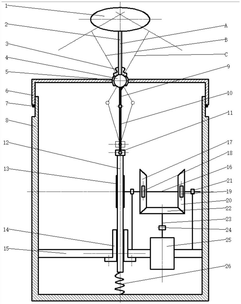
[0043] combine figure 1 It can be seen that the swing type wave energy power generation system of the present invention includes a wave energy collection system, a conversion system and a generator part.

[0044] The wave energy harvesting system described in this embodiment includes: a buoy 1 , a swing rod 2 , a spherical hinge 4 and a housing. The float 1 is fixedly connected with the swing rod 2, and the swing rod 2 is fixed on the spherical hinge 4.

[0045] The shell is a hollow cylindrical structure, including an upper shell 6 , a lower shell 8 , a corrugated hose 3 , an annular hoop 5 and a sealing ring 7 . One end of the corrugated hose 3 is fixed on the swing rod 2, and the other end is fixed on the ring hoop 5, which is used for sealing the spherical hinge 4. The ring hoop 5 is installed on the upper shell 6 and contacts with the curved surface of the spherical hinge 5; the upper shell The inner surface of the body 6 is slidingly connected with the outer surface of...

Embodiment 2

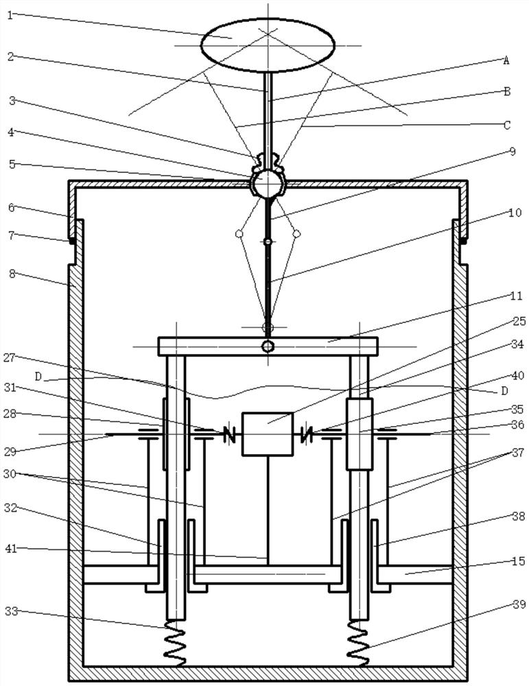
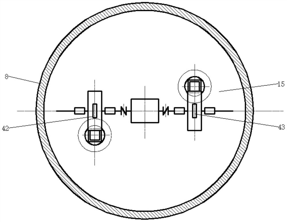
[0057] combine figure 2 and 3 It can be seen that the swing type wave energy power generation system of the present invention is characterized in that it includes a wave energy collection system, a conversion system and a generator part.

[0058] The wave energy collection system is the same as in Embodiment 1, the difference being the difference in the conversion system;

[0059] The conversion system in this embodiment includes: a slider crank mechanism and a transmission mechanism composed of a pair of rack gears and their supports. The slider crank mechanism includes a crank 9 , a connecting rod 10 and a slider 11 . The pair of transmission mechanisms includes: left rack 27, left spur gear 28, left one-way clutch 42, left gear shaft 29, a pair of left gear shaft support 30, left sleeve 32 and left limit spring 33; Rack 34, right spur gear 35, right one-way clutch 43, right gear shaft 36, a pair of right gear shaft supports 37, right sleeve 38 and right limit spring 39....

Embodiment 3

[0065] combine Figure 4 , 5 It can be known from and 6 that the swing type wave energy power generation system of the present invention is characterized in that it includes a wave energy collection system, a conversion system and a generator part.

[0066] The wave energy harvesting system is the same as that in Embodiment 1.

[0067] The conversion system includes: a crank slider mechanism, a pair of worm and gear transmission systems and a transmission mechanism composed of supporting parts. The slider crank mechanism includes a crank 9 , a connecting rod 10 and a slider 11 . The pair of transmission mechanisms includes: a front worm 48 , a front worm wheel 49 , a front one-way clutch 50 , a rear worm 47 , a rear worm wheel 46 , a rear one-way clutch 45 and a worm shaft 44 .

[0068]The front worm 48 and the rear worm 47 are respectively provided with one, and one end of the front worm 48 and the rear worm 47 is fixed on the slider 11 by a pair of worm fixing nuts 52, an...


PUM


Abstract

The invention discloses an oscillating wave energy generation system and an aircraft. The oscillating wave energy generation system comprises a wave energy collecting system, a conversion system and agenerator part, wherein the wave energy collecting system comprises a variable-propeller device, an oscillating bar, a spherical hinge, a spherical hoop and a sealed cabin, and wave energy in all directions can be collected; the conversion system comprises three different conversion mechanisms, and the left-and-right oscillation of a paddle can be converted into the up-and-down reciprocating motion of a sliding block to the continuous rotating motion of an output end and the speed increasing function; and the generator part comprises an output shaft, a coupling and a generator, and the generator is connected with an output bevel gear by virtue of a connecting shaft, so that the conversion from mechanical energy to electric energy is realized. The oscillating wave energy generation systemhas the advantage of convenience in manufacturing, installation and maintenance and is not influenced by the wave direction, small wave movement in a horizontal plane can be caught, and power is generated.

Description

technical field [0001] The invention belongs to the field of new renewable energy technology and marine equipment, and specifically relates to a swing-type wave energy power generation system and an aircraft. Background technique [0002] With the shortage of energy and the deterioration of the ecological environment, countries around the world have generally realized the importance of new energy power generation technology, and have carried out a lot of research and development work in the fields of wind energy, ocean energy, and solar energy. Ocean energy is rich in wave energy and can be used for new energy power generation. However, waves are complex irregular waves with scattered energy and low frequency, making them difficult to collect, resulting in low efficiency of wave energy generation equipment. Therefore, it is of great significance to design a high-efficiency power generation system for the development and utilization of wave energy. [0003] At present, the ...

Claims


Application Information

Patent Timeline
Patent Type & Authority Patents(China)
IPC IPC(8): F03B13/18F03B11/00
CPCF03B11/00F03B13/1815Y02E10/20Y02E10/30
Inventor 杨富春张悦
Owner SHANDONG UNIV
Why Eureka
Try Eureka