Drilling device for brake pad steel backing

A drilling device and brake pad technology, applied in feeding devices, boring/drilling, automatic control devices, etc., can solve the problem of increasing capital investment, management costs and mold storage costs, and is not suitable for small batches and multi-variety modern manufacturing requirements , It is difficult to adapt to problems such as frequent product updates, to achieve the effect of saving debugging time, high degree of automation, and less processing time

Active Publication Date: 2019-10-11
SHANDONG ACAD OF SCI INST OF AUTOMATION
View PDF9 Cites 0 Cited by
  • Summary
  • Abstract
  • Description
  • Claims
  • Application Information

AI Technical Summary

Problems solved by technology

The inventor found that the existing equipment needs a long period of debugging before each type of processing is changed, it is difficult to adapt to the frequent u

Method used


Image

  • Drilling device for brake pad steel backing
  • Drilling device for brake pad steel backing
  • Drilling device for brake pad steel backing

Examples


Example Embodiment

[0042] Example 2:

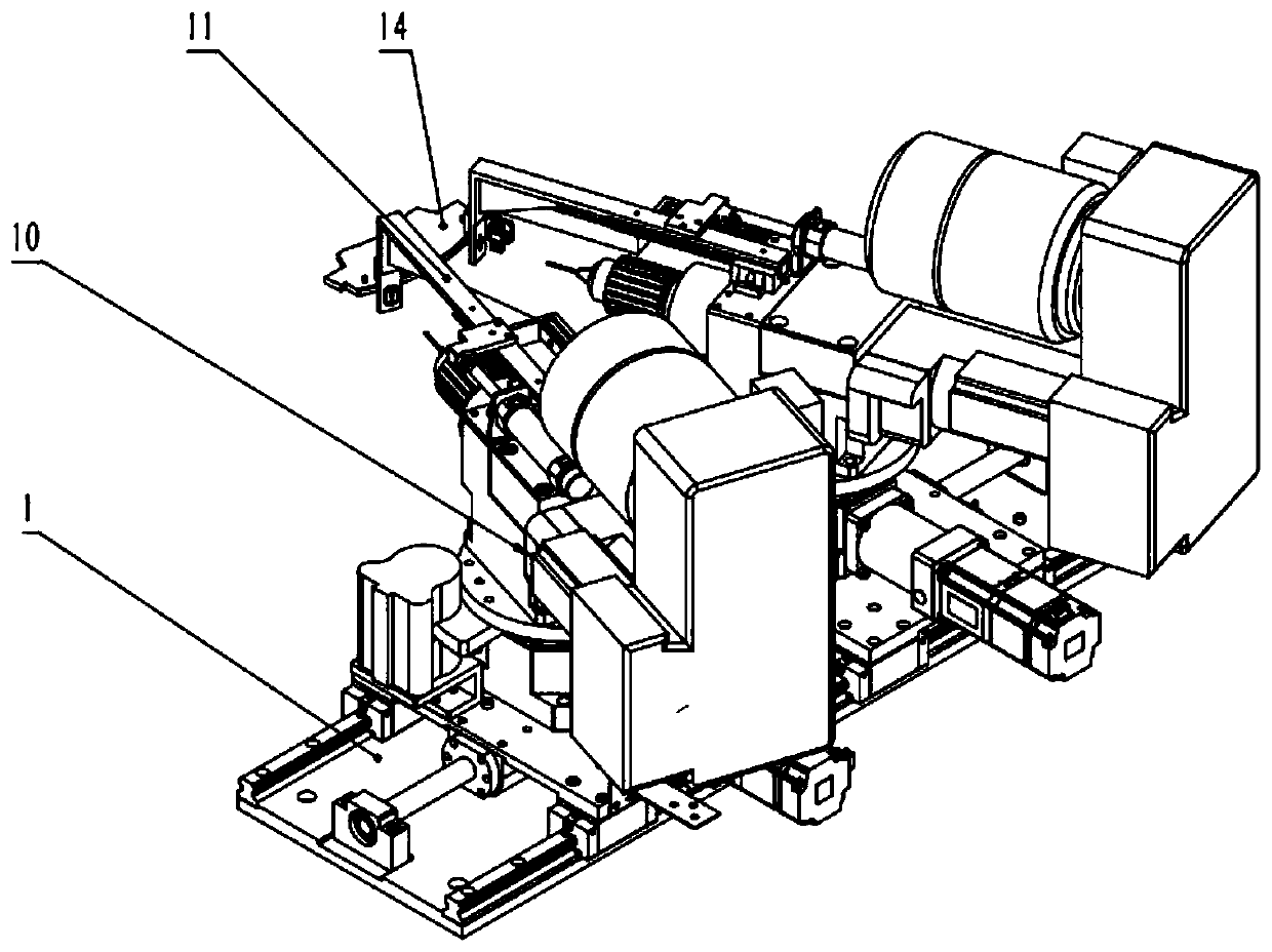
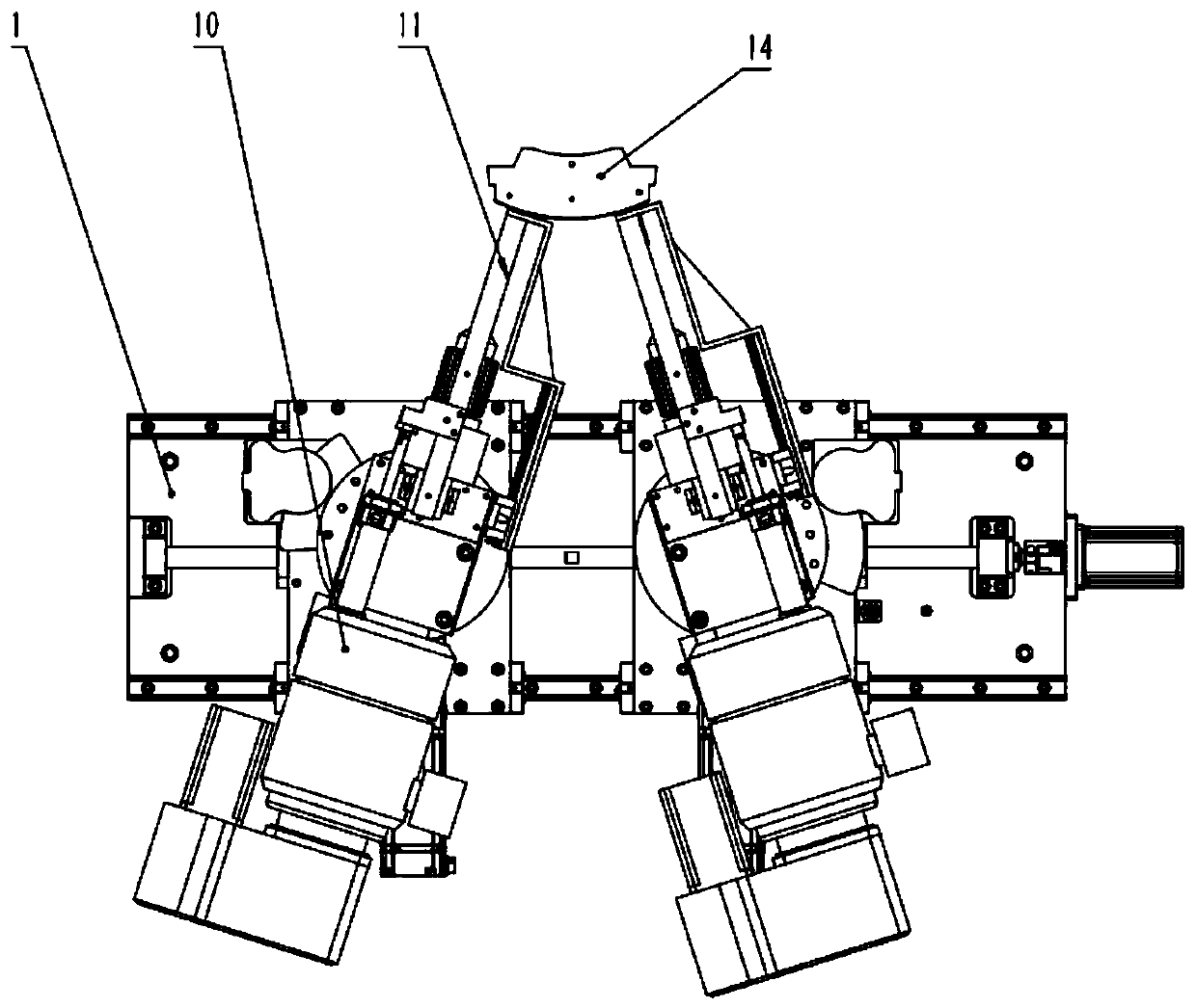
[0043] This embodiment discloses a working method of a brake pad steel back drilling device: the first driving mechanism drives the first drilling assembly and the second drilling assembly to move, so that the first drilling assembly and the second drilling The symmetry line of the assembly coincides with the centering axis of the steel back 14 of the brake pad to be drilled. The rotating platform drives the second drive mechanism and the drill bit to rotate to the preset position to realize the drilling angle positioning, and the pneumatic butterfly brake clamps the brake. The tightening plate restricts the further rotation of the second driving mechanism and the drill bit. The cylinder drives the top tightening plate to move. The vertical plate extends forward and contacts the arc surface of the brake pad steel back. The vertical plate is used to fasten and fix the brake pad steel back. When the second driving mechanism starts to work, the drill bit is exten...


PUM


Abstract

The present invention relates to a drilling device for a brake pad steel backing, comprising a plurality of drilling assemblies and a tightening mechanism, wherein the drilling assemblies are connected with a first driving mechanism, the first driving mechanism is capable of driving the adjacent drilling assemblies move towards or against each other; the drilling assemblies comprise a slewing mechanism connected with the first driving mechanism, the slewing mechanism is connected with a drilling bit assembly for driving rotation of the drilling bit assembly; the drilling bit assembly comprisesa drilling bit, and a second driving mechanism connected with the drilling bit, the second driving mechanism is fixedly connected with the slewing mechanism for driving the rotation of the drilling bit around the drilling bit axis and the feeding movement along the drilling bit axis. The tightening mechanism is arranged on one side of the drilling assemblies, comprising a third driving mechanism,and a tightening member connected with the third driving mechanism, the third driving mechanism is capable of driving the tightening member to tighten the brake pad steel backing to be drilled. The drilling device disclosed by the present invention has the beneficial effects of reducing the processing cost of the brake pad steel backing, thereby greatly reducing time for tool bit alignment.

Description

technical field [0001] The invention relates to the technical field of metal processing equipment, in particular to a brake pad steel back drilling device. Background technique [0002] The steel back of the brake pad and the friction material are composed of the brake pad through heat bonding technology, which is mainly used in the braking system of the car. The steel back is a fan-shaped carbon steel sheet, and usually two holes with a diameter of 2 or 2.5 mm need to be symmetrically drilled on the fan-shaped arc surface as the installation holes for the friction limiter. Due to the large number of car models, there are many varieties and specifications of the matching brake pads. The steel backs of each brake pad have different shapes, and the positions and angles of the processing holes are different. At present, the existing drilling equipment for the steel back of the brake pad usually adopts the fixed mold method, and each steel back needs to make a special positioni...

Claims


Application Information

Patent Timeline
IPC IPC(8): B23B41/00B23B49/00B23Q1/26B23Q15/22
CPCB23B41/00B23B49/00B23Q1/26B23Q15/22
Inventor 孙洁闫九祥李倩王其林赵永国
Owner SHANDONG ACAD OF SCI INST OF AUTOMATION
Why Eureka
Try Eureka