
A method for determining the length of the spliced ​​plate of the lower flange of the beam-column upper welded lower bolt joint based on the energy dissipation target

A splicing plate and flange technology, applied in the directions of architecture, geometric CAD, building structure, etc., can solve the problem of not considering the energy consumption of nodes, not clearly specifying the size of the splicing plate of the lower flange of the steel beam, and not specifying the inner flange of the node. Dimensions of cover, backing and web shears and their determination methods

Active Publication Date: 2021-03-30
青岛中青杭萧绿色建筑科技有限公司 +1
View PDF2 Cites 0 Cited by
  • Summary
  • Abstract
  • Description
  • Claims
  • Application Information

AI Technical Summary

Problems solved by technology

In the patent 201710903060.8, the inventor of this patent proposed a method of manufacturing beam-column joints with flange bolted and welded hybrid connections, and calculated the number of high-strength bolts on the lower flange of the frame beam and the length of the weld at the splicing plate on the lower flange of the cantilever beam , the components are processed in the factory, hoisted and assembled in place at the construction site, however, it is not clearly stated how to determine the size of the splice plate of the lower flange of the steel beam, and the energy consumption of the nodes is not considered
Patent CN109629684A discloses a reversible assembled anti-buckling trough web shear member beam-column node connection device, the node is a combination of beam end reinforcement and flange cover plate connection weakening, which can realize multiple energy consumption mechanisms, After the earthquake, the function of the structure can be restored only by replacing the connecting plate, but the dimensions and determination methods of the inner cover plate, backing plate and web shearing parts of the joint flange are not explained

Method used


Image

  • A method for determining the length of the spliced ​​plate of the lower flange of the beam-column upper welded lower bolt joint based on the energy dissipation target
  • A method for determining the length of the spliced ​​plate of the lower flange of the beam-column upper welded lower bolt joint based on the energy dissipation target
  • A method for determining the length of the spliced ​​plate of the lower flange of the beam-column upper welded lower bolt joint based on the energy dissipation target

Examples


Embodiment

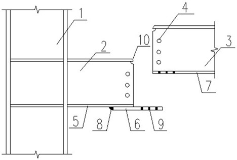
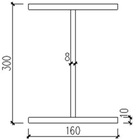
[0080] A beam-column upper-welding bolt joint, comprising a steel column 1, a cantilever beam 2, a frame beam 3, a web splicing bolt 4, a cantilever beam lower flange 5, a splicing plate 6, a frame beam lower flange 7, and a splicing plate 6 The fillet weld 8 connecting the lower flange of the cantilever beam 5, the high-strength bolt 9 connecting the splicing plate 6 and the lower flange of the frame beam 7, and the connecting weld 10 between the upper flange of the cantilever beam and the upper flange of the frame beam, among which, Q345B is used for beam and column steel Hot-rolled H-shaped steel, Q235 hot-rolled H-shaped steel is used for splicing plate 6, the cross-sectional dimensions of cantilever beam 2 and frame beam 3 are both HN300mm×160mm×8mm×10mm, and the cross-sectional dimension of column 1 is HW250mm×250mm×9mm×14mm; 10.9 grade M20 friction type high-strength bolts 9, the diameter of the bolt hole of the test piece is 21.5mm; the size of the web gusset plate is 2...


PUM


Abstract

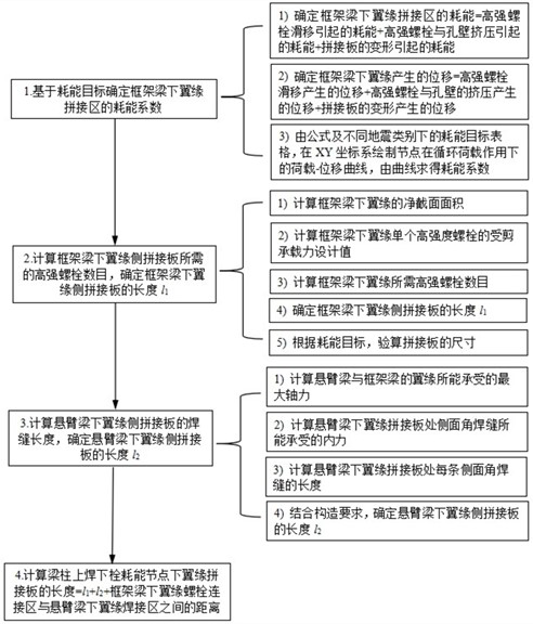
The present invention relates to a method for determining the length of the spliced ​​plate of the lower flange of a beam-column upper welded lower bolt joint based on an energy consumption target. The following steps are adopted: based on the energy consumption target, the load-displacement of the node under cyclic load is drawn in the XY coordinate system Curve, the energy dissipation coefficient of the splicing area of ​​the lower flange of the frame beam is calculated from the curve; the length of the splicing plate on the lower flange side of the frame beam is determined, and the size of the splicing plate is checked and calculated according to the energy consumption target; the splicing plate on the lower flange side of the cantilever beam is determined Finally, determine the length of the spliced ​​plate of the lower flange of the beam-column upper welded lower bolt joint. In the design process of beam-column upper and lower bolt joints, if the spliced ​​plate is too short, the bearing capacity of the joint will be insufficient; if the spliced ​​plate is too long, the welding stress will be concentrated, the residual deformation will increase, and the lower flange plate and the spliced ​​plate will be buckled and unstable. For the above deficiencies, the present invention proposes a method for determining the length of the spliced ​​plate, which can ensure the bearing capacity, ductility and energy dissipation capacity of the upper and lower bolt joints of beams and columns, and reduce welding stress concentration and residual deformation.

Description

technical field [0001] The invention belongs to the field of design of beam-column joints of building steel structure frames, and in particular relates to a method for determining the length of splice plates of lower flanges of beam-column upper-weld lower-bolt joints based on energy consumption targets. Background technique [0002] With the improvement of economic construction on building structure and function requirements, steel structure has developed from being mainly used in the field of industrial plants in the past to now widely used in public buildings and civil buildings. The prefabricated steel structure is a building made by producing some or all of the components in the building in the factory, and then transported to the construction site for assembly. It has the advantages of short construction period, labor saving, pollution reduction and environmental protection. It is a modern building structure. Direction of development. [0003] In the fabricated steel ...

Claims


Application Information

Patent Timeline
Patent Type & Authority Patents(China)
IPC IPC(8): G06F30/17E04B1/24E04B1/58
CPCE04B1/2403E04B2001/2406E04B2001/2415E04B2001/2418G06F30/17
Inventor 郁有升郭亚楠于德湖王燕
Owner 青岛中青杭萧绿色建筑科技有限公司
Learn More