Mechanical-hydraulic combined rock breaking TBM tunneling equipment and tunneling method thereof

A hydraulic and mechanical technology, applied in the field of mechanical-hydraulic combined rock-breaking TBM tunneling equipment, can solve problems such as unfavorable realization and application, failure to achieve the expected effect, and the maximum force of the rock, so as to achieve uniform coverage of the mechanical cutter with water mist , Improve rock breaking efficiency and reduce mechanical wear

Pending Publication Date: 2019-10-11
INST OF ROCK AND SOIL MECHANICS - CHINESE ACAD OF SCI
View PDF2 Cites 10 Cited by
  • Summary
  • Abstract
  • Description
  • Claims
  • Application Information

AI Technical Summary

Problems solved by technology

[0008] However, if the above-mentioned first rock-breaking method is used to break rocks, the maximum force required to break rocks is relatively large, and the hob is easy to wear, so the rock-breaking efficiency is low;
[0009] Use the above-mentioned second rock-breaking method to break rocks. For example, the application number is: 201310188881.X, and the patent name is "Arrangement Method and Structure of High-Pressure Water Jet in TBM Cutterhead"; it is in the main structural form of traditional TBM cutterhead Basically, a number of high-pressure water nozzles are randomly arranged in the blank positions of the TBM cutter head, which can improve the rock-breaking efficiency of the TBM, reduce the temperature of the cutter head, and prevent dust and cool the environment; however, because it needs to be specially installed on the TBM cutter head The opening of the

Method used


Image

  • Mechanical-hydraulic combined rock breaking TBM tunneling equipment and tunneling method thereof
  • Mechanical-hydraulic combined rock breaking TBM tunneling equipment and tunneling method thereof
  • Mechanical-hydraulic combined rock breaking TBM tunneling equipment and tunneling method thereof

Examples


Embodiment Construction

[0096] The implementation of the present invention will be described in detail below in conjunction with the accompanying drawings, but they do not constitute a limitation to the present invention, and are only examples. At the same time, the advantages of the present invention are clearer and easier to understand through the description.

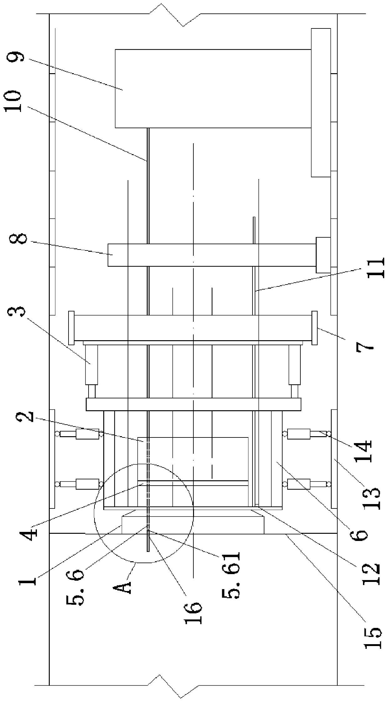
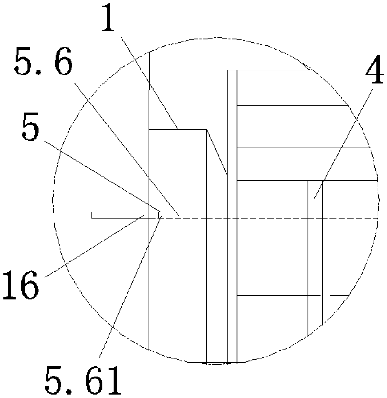
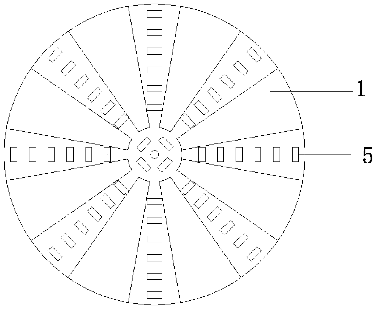
[0097] Referring to the accompanying drawings, it can be seen that the mechanical-hydraulic combined rock-breaking TBM excavation equipment includes a cutter head 1, a rotary drive 2, a propulsion cylinder 3, a water jet rotation adjustment part 4 and a hydraulic cutting hob tool 5;

[0098]The hydraulic cutting hob cutter 5 is arranged on the cutter head 1 along the circumferential direction;

[0099] The rotary drive 2 is located at the rear end of the cutterhead 1; the rotary drive controls the rotation of the cutterhead of the combined rock-breaking TBM, and pushes the cylinder to push the TBM cutterhead forward;

[0100] The propulsio...


PUM


Abstract

The invention discloses mechanical-hydraulic combined rock breaking TBM tunneling equipment. The mechanical-hydraulic combined rock breaking TBM tunneling equipment includes a cutter head, a rotary driving device, a propulsion cylinder, a hydraulic cutter rotation adjustment part and hydraulic cutting hob cutters; the hydraulic cutting hob cutters are disposed on the cutter head along the circumference; the hydraulic cutter rotation adjustment part is located at a front portion of the rotary driving device; an outer frame is located outside the rotary driving device; an outer frame upper supporting shoe is located behind the outer frame; a rear support and a water tank are located behind the outer frame upper supporting shoe, and the rear support is located between the outer frame upper supporting shoe and the water tank; a hydraulic cutter external water pipe is arranged on the water tank; and the water tank and the hydraulic cutting hob cutters are connected through the hydraulic cutter external water pipe and the hydraulic cutter rotation adjustment part. The mechanical-hydraulic combined rock breaking TBM tunneling equipment has the advantages of suitable penetration degree, high rock breaking efficiency and less energy consumption of rock breaking. The invention also discloses a tunneling method of the mechanical-hydraulic combined rock breaking TBM tunneling equipment.

Description

technical field [0001] The invention relates to the field of tunnels and underground engineering, in particular to the field of TBM tunnel construction under complex geological conditions. More specifically, it is mechanical-hydraulic combined rock-breaking TBM tunneling equipment. The invention also relates to a tunneling method of TBM tunneling equipment for combined mechanical-hydraulic rock breaking. Background technique [0002] The traditional TBM uses a mechanical hob to break rock, and the TBM hob often has three states when breaking rock, namely, small penetration, proper penetration and excessive penetration. [0003] Under the condition of a certain hob spacing, if the penetration is too small, the cracks generated under the cutter head will expand to the free surface of the broken rock (hole face) and form triangular rock slag flakes, or the cracks formed by two adjacent hobs. The generated horizontal cracks cannot intersect, and the rock ridge between the hobs...

Claims


Application Information

Patent Timeline
IPC IPC(8): E21D9/087E21D9/10E21D9/12
CPCE21D9/003E21D9/087E21D9/1066E21D9/12
Inventor 周辉徐福通卢景景张传庆邱浩权高阳
Owner INST OF ROCK AND SOIL MECHANICS - CHINESE ACAD OF SCI
Why Eureka
Try Eureka