Intelligent temperature control system of UAV engine and its realization method

A technology of intelligent temperature control and unmanned aerial vehicles, which is applied in the cooling of engines, machines/engines, and power plant cooling systems. problem, achieve the effect of reducing engine load, improving cooling effect, and avoiding overheating and scuffing

Active Publication Date: 2020-10-16
青岛未来创新高新技术有限公司
View PDF5 Cites 0 Cited by
  • Summary
  • Abstract
  • Description
  • Claims
  • Application Information

AI Technical Summary

Problems solved by technology

[0004] 1. Natural cooling is greatly affected by the external ambient temperature, and the cooling efficiency is low, which cannot meet high temperature weather and long-term operation;
[0005] 2. The fan cooling system with forced air cooling, on the one hand, will increase the extra weight of the engine and reduce the power-to-weight ratio of the engine; Poor reliability;
[0006] 3. The forced air cooling is an open-loop control, which cannot be changed with the change of the external environment temperature, and the fan generates a lot of heat and has poor cooling effect when it runs for a long time;
[0007] 4. The liquid-cooled heat dissipation coolant is easy to leak and is easily affected by climate change. For example, the temperature is low in winter, and the engine needs a long time to warm up the car before it can run normally

Method used


Image

  • Intelligent temperature control system of UAV engine and its realization method
  • Intelligent temperature control system of UAV engine and its realization method
  • Intelligent temperature control system of UAV engine and its realization method

Examples


Embodiment Construction

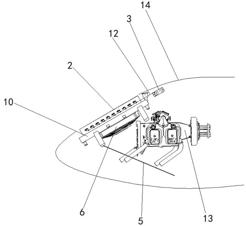
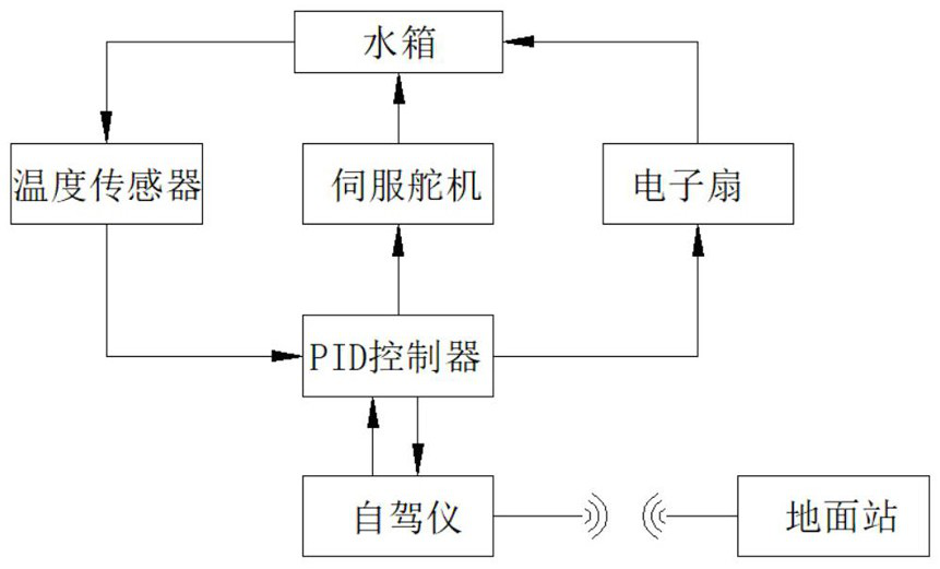
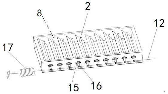
[0033] Such as Figure 1-7 As shown, the intelligent temperature control system of the UAV engine provided by the present invention includes an intelligent water tank assembly 11 installed on the head 14 of the UAV and a PID controller integrated inside the UAV autopilot. The rear intelligent water tank assembly is at a certain angle of inclination with the horizontal plane. The intelligent water tank assembly mainly includes a water tank 10, a louver movable assembly installed on the top of the water tank, and an electronic fan 6 installed at the bottom of the water tank. When the engine is overloaded, the electronic fan is controlled by the PID controller to rotate to achieve rapid heat dissipation of the water tank. In a specific embodiment of the present invention, the water tank is installed above the engine 13 through a bracket 5 and is connected with the engine. A temperature sensor 1 is arranged at the water inlet of the water tank. The temperature sensor is used to co...


PUM


Abstract

The invention discloses an intelligent temperature control system of an unmanned aerial vehicle engine and an implementation method of the intelligent temperature control system, relates to the technical field of unmanned aerial vehicle engines, and in particular to an unmanned aerial vehicle engine liquid cooling (water cooling and oil cooling) temperature control system and an implementation method thereof. The intelligent temperature control system comprises an intelligent water tank assembly installed on a machine head portion of an unmanned aerial vehicle and a PID controller integrated in an unmanned aerial vehicle self-driving instrument, wherein the intelligent water tank assembly comprises a water tank, a shutter movable assembly arranged at the top of the water tank and an electronic fan arranged at the bottom of the water tank, the water tank is arranged above the engine and is connected with the engine, a temperature sensor is arranged at the water inlet of the water tank,a heating rod is arranged at the water outlet of the water tank, a servo motor in the heating rod, the temperature sensor, the shutter movable assembly and an electronic fan are connected with the PIDcontroller, and the PID controller completes real-time data transmission communication with the ground end through a radio station inside the unmanned aerial vehicle self-driving instrument. The system has the positive effect on improving the cooling effect of the unmanned aerial vehicle engine.

Description

technical field [0001] The invention relates to the technical field of drone engines, in particular to a liquid-cooled (water-cooled, oil-cooled) temperature control system for drone engines and an implementation method thereof. Background technique [0002] The UAV engine cooling system (hereinafter referred to as the UAV cooling system) is an important part of the UAV. Its function is to cool the excess heat generated during the operation of the engine and maintain the engine temperature within a certain range to ensure the continuous and stable operation of the engine. , its cooling effect directly determines the reliability and service life of the UAV engine. [0003] At present, the cooling system of drones mainly includes natural cooling, forced air cooling and liquid cooling. Natural cooling is through the heat sink of the engine block in contact with the outside air. When the engine is working, the natural wind flows to cool the engine; forced air cooling is more nat...

Claims


Application Information

Patent Timeline
Patent Type & Authority Patents(China)
IPC IPC(8): F01P11/00F01P5/02F01P11/20F01P7/08B64D33/08B64D33/10
CPCB64D33/08B64D33/10F01P5/02F01P7/08F01P11/00F01P11/20
Inventor 马张文
Owner 青岛未来创新高新技术有限公司
Why Eureka
Try Eureka