Heat exchanger core and heat exchanger based on bionic stacking three-dimensional configuration

A three-dimensional configuration and heat exchanger technology, applied in the direction of indirect heat exchangers, heat exchanger types, heat exchange equipment, etc., can solve the problems of medium import and export restrictions, limited flow channel form, fuel medium coking, etc. Installation space, simple structure, and improved heat transfer power

Active Publication Date: 2020-07-17
陕西益信伟创智能科技有限公司
View PDF1 Cites 0 Cited by
  • Summary
  • Abstract
  • Description
  • Claims
  • Application Information

AI Technical Summary

Problems solved by technology

[0005] (3) Micro-channel heat exchanger: The micro-channel heat exchanger improves the heat exchange capacity by increasing the number of channels and reducing the hydraulic diameter, but because the hydraulic diameter of the channel is too small, it also has coking and clogging for the fuel medium risks of
Due to the discontinuity and limited thickness of the transverse and longitudinal corrugations, the pressure that the corrugated plates can bear is limited, and the diffusion welding process is not suitable, resulting in poor compressive strength; the flow direction on both sides is limited, that is, it must be staggered flow , so that the setting of the medium inlet and outlet is limited; the number of plate layers in a heat exchange unit is limited (two layers), and the form of the constructed flow channel is limited, which makes it difficult to greatly increase the heat exchange power; the above factors make the application scene restricted. Larger limitations, especially in the aerospace field with high heat flux, it is difficult to apply

Method used


Image

  • Heat exchanger core and heat exchanger based on bionic stacking three-dimensional configuration
  • Heat exchanger core and heat exchanger based on bionic stacking three-dimensional configuration
  • Heat exchanger core and heat exchanger based on bionic stacking three-dimensional configuration

Examples


Embodiment 1

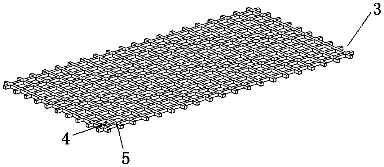
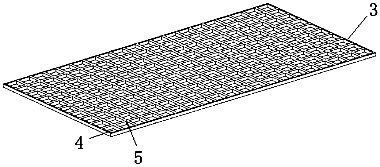
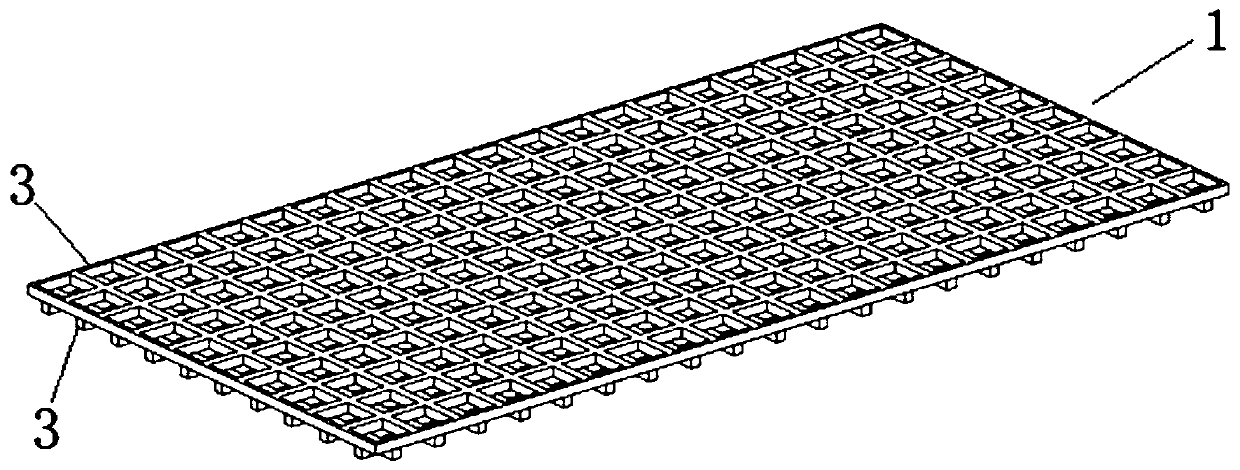
[0046] Heat exchanger core body of the present invention, as Figure 1-5As shown, it consists of multiple heat exchange units 1 stacked, each heat exchange unit 1 includes two layers of mesh plates 3, and a plurality of grids 4 are evenly distributed on the opposite end surfaces of the mesh plates 3, and the two layers of mesh The mesh rib nodes 5 of the plates 3 are interlaced (that is, the mesh rib nodes 5 of one layer of mesh plates 3 cannot overlap with the mesh rib nodes 5 of another layer of mesh plates 3), forming many interconnected flow channels and Chamber; thereby realizing a huge increase in the heat exchange surface and volume ratio, two adjacent heat exchange units 1 respectively constitute a cold-side medium flow chamber 6 and a hot-side medium flow chamber 7 for heat exchange; the mesh plate 3 The edge is provided with a frame 2 for edge sealing to prevent medium leakage. The cold side medium flow chamber 6 communicates with the cold medium through the inlet an...

Embodiment 2

[0049] Another structure of the heat exchanger core of the present invention, such as Figure 6-7 As shown, the bottom of the grid 4 is a through hole, so that both sides of the mesh plate 3 have the grid 4 with the same structure, and two or more layers of mesh plates 3 are stacked to form a single heat exchange unit 1, such as Figure 6-7 As shown, the exterior of a single heat exchange unit 1 is provided with a partition to prevent medium leakage; the stacking of multi-layer mesh plates 3 can further expand the heat exchange area of ​​the heat exchange unit 1 per unit volume and improve heat exchange performance. The thickness of the mesh plates 3 of the same heat exchange unit 1 or different heat exchange units 1 may be equal or different, and the calculation and selection shall be carried out according to actual use requirements.

Embodiment 3

[0051] Alternative structures for the heat exchanger core of the present invention, such as Figure 8-9 As shown, the grid 4 of the mesh plate 3 is hexagonal, two layers of mesh plates 3 are stacked, and the rib nodes 5 of the two layers of mesh plates 3 are interlaced to form a more complex interconnected flow. Roads and chambers; among two adjacent layers of mesh plates 3, the rib node 5 of one layer of mesh plates 3 is located at the centroid of the grid 4 of the other layer of mesh plates 3.

[0052] The alternative scheme of the heat exchanger core based on the bionic stacked three-dimensional configuration of the present invention:

[0053] Grid 4 is a closed shape composed of straight lines and / or curves. Unclosed parts have poor mechanical properties and are difficult to weld and form; grid 4 is any one of triangles, rectangles, pentagons, hexagons or other polygons type; the grid 4 is any one of sector, ellipse, circle or other arc shapes.

[0054] Among the adjacen...


PUM


Abstract

The invention discloses a heat exchanger core body based on bionic stacking three-dimensional configuration and a heat exchanger. The heat exchanger core body is formed by stacking a plurality of heatexchange units, each heat exchange unit comprises two layers of net-shaped plates, a plurality of grids are uniformly distributed on the opposite end faces of the net-shaped plate pieces, net rib nodes of the two layers of net-shaped plates are staggered with each other, and a plurality of flow passages and chambers communicating with each other are formed; and every two adjacent heat exchange units forms a cold side medium flow cavity and a hot side medium flow cavity. According to the heat exchanger core body, a plurality of micro cavities communicating with each other are formed in the medium flowing cavities to form a bionic bone marrow structure, and the bionic bone marrow structure has relatively large ratio surface area to volume, compared with a heat exchanger with an internal straight flow channel, the heat exchange power can be improved by 20% or more, and the weight of the heat exchanger is reduced by 20% or more; and the compactness of the heat exchanger is improved to be6 times or more of the compactness of a tube-shell heat exchanger, the heat exchanger can bear high pressure of about 20 MPa, has relatively high heat exchange efficiency under the condition that thehydraulic diameter is large, and is suitable for large heat flux density application scenes.

Description

technical field [0001] The invention belongs to the technical field of heat exchange equipment, and relates to a heat exchanger core and a heat exchanger based on a bionic stacked three-dimensional configuration. Background technique [0002] In order to solve the high heat flux heat dissipation problem in the aerospace field, it is necessary to design a lightweight and efficient heat exchanger. Currently available solutions are as follows: [0003] (1) Tube / shell heat exchanger: tube / shell heat exchanger is a widely used and mature heat exchanger in the industry. However, when it is applied in the aerospace field, due to its The compactness is not high, and the heat exchange capacity is limited, which often leads to problems of excessive volume or weight. This is limited by its own structural characteristics. In addition, in order to improve its compactness, the heat exchange area per unit volume can only be increased by continuously reducing the inner diameter of the tu...

Claims


Application Information

Patent Timeline
Patent Type & Authority Patents(China)
IPC IPC(8): F28F3/02F28D9/00
CPCF28D9/00F28F3/02
Inventor 罗遥远王俊伟
Owner 陕西益信伟创智能科技有限公司
Why Eureka
Try Eureka