
Three-phase high-speed rotation positive electrode driver

A high-speed rotation and drive technology, which is applied in AC motor control, radiological diagnostic equipment, medical science, etc., can solve problems such as limited reconstruction space, crack damage on the target surface, and irregular scattering of rays to improve imaging effects , prolong the service life, the effect of smooth current transition

Inactive Publication Date: 2019-10-11
NANNING YIJU MEDICAL ELECTRONICS
View PDF2 Cites 1 Cited by
  • Summary
  • Abstract
  • Description
  • Claims
  • Application Information

AI Technical Summary

Problems solved by technology

[0003] In the past tubes, the anode target surface of the tube can only reach 3600 rpm under the drive of the power frequency motor; It ranges from AC160V to 220V, and the working frequency is 50 / 60Hz, so that the motor speed is limited to 3000-3600 rpm; because the anode target surface rotates too slowly, it is easy to produce the following adverse effects:
[0004] 1. It is easy to cause the target surface to be heated unevenly under the bombardment of electrons, causing cracks and damage to the target surface, resulting in irregular scattering of rays, which affects the imaging effect of X-ray images
[0005] 2. A certain area of ​​the target surface is bombarded by the electron beam for a long time and the metal surface is melted by the high temperature generated. Under the action of the rotating centrifugal force, the melted high-temperature metal liquid is splashed onto the glass wall of the ball tube, which directly leads to the damage of the whole ball tube. scrapped
The first method cannot be further improved because the structure of the tube is fixed and the space for modification is limited.

Method used


Image

  • Three-phase high-speed rotation positive electrode driver
  • Three-phase high-speed rotation positive electrode driver
  • Three-phase high-speed rotation positive electrode driver

Examples


Embodiment

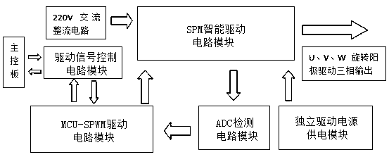
[0040] Such as figure 1 As shown, a three-phase high-speed rotating anode driver is mainly composed of an MCU-SPWM drive circuit module, an SPM intelligent drive circuit module, an ADC detection circuit module, an independent drive power supply module and a drive signal control circuit module; the drive The signal control circuit module, the MCU-SPWM drive circuit module, and the SPM intelligent drive circuit module are connected sequentially; the SPM intelligent drive circuit module is also connected with the ADC detection circuit module and the independent drive power supply module respectively; the ADC detection The circuit module is also connected with the MCU-SPWM driving circuit module.

[0041] exist figure 1 Among them, the main control board inputs drive control instructions to the MCU-SPWM drive circuit module through the drive signal control circuit module, and the external mains supplies the drive voltage to the SPM intelligent drive circuit module after passing t...


PUM


Abstract

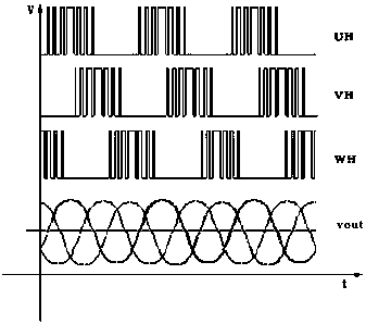
The invention discloses a three-phase high-speed rotation positive electrode driver. The three-phase high-speed rotation positive electrode driver mainly comprises an MCU-SPWM driving circuit module,a SPM intelligent driving circuit module, an ADC detection circuit module, an independent driving power supply module and a driving signal control circuit module, wherein the driving signal control circuit module, the MCU-SPWM driving circuit module and the SPM intelligent driving circuit module are sequentially connected, the SPM intelligent driving circuit module is further connected with the ADC detection circuit module and the independent driving power supply module, and the ADC detection module is further connected with the MCU-SPWM driving circuit. A SPWM pulse waveform at 50-180Hz generated by a singlechip microcomputer (MCU) is mainly used, a post-stage FSBS15CH60 intelligent driving circuit module is controlled to generate an alternating current so as to drive the motor to rotateby driving and amplification, the rotation speed of a target surface can be effectively increased, the imaging effect is improved, the target surface is prevented from being easily damaged by an electronic beam, and the service lifetime of equipment is prolonged.

Description

technical field [0001] The invention relates to a high-speed rotating anode driver for a medical high-frequency X-ray machine, belonging to the technical field of X-ray machine equipment. Background technique [0002] With the continuous development of medical technology in the world, the diagnosis and treatment methods used in medical diagnosis are also changing with each passing day, and the technology is constantly being updated. Similarly, the imaging equipment used in the radio frequency imaging X-ray diagnostic system has also undergone revolutionary changes. The high voltage generator The working frequency has changed from the initial 50Hz power frequency to today's 400KHz or even higher frequency, which makes the X-ray imaging quality clearer and more stable, the patient receives a lower X-ray radiation dose, the space occupied by the machine and equipment is greatly reduced, and the equipment is more controllable. Among them, in the X-ray diagnosis and treatment equ...

Claims


Application Information

Patent Timeline
Patent Type & Authority Applications(China)
IPC IPC(8): H02P27/08H05G1/30A61B6/00
CPCA61B6/40H02P27/08H05G1/30
Inventor 蒋健马培威
Owner NANNING YIJU MEDICAL ELECTRONICS
Learn More