Travel reducer test system

A technology of walking reducer and test system, which is applied in the direction of machine gear/transmission mechanism testing, thermometer parts, measuring devices, etc. It can solve the problems of low efficiency, large cost investment, and large space occupation, so as to reduce energy consumption, The effect of easy operation and reduced equipment investment

Active Publication Date: 2019-10-15
SHAANXI FAST AUTO DRIVE GROUP CO LTD
View PDF6 Cites 6 Cited by
  • Summary
  • Abstract
  • Description
  • Claims
  • Application Information

AI Technical Summary

Problems solved by technology

[0004] The purpose of the present invention is to solve the deficiencies of the existing travel reducer test system, such as large cost investment, large occupied space, low efficiency, etc., and provides a travel reducer test system

Method used


Image

  • Travel reducer test system
  • Travel reducer test system
  • Travel reducer test system

Examples


Embodiment Construction

[0028] Below in conjunction with accompanying drawing and specific embodiment content of the present invention is described in further detail:

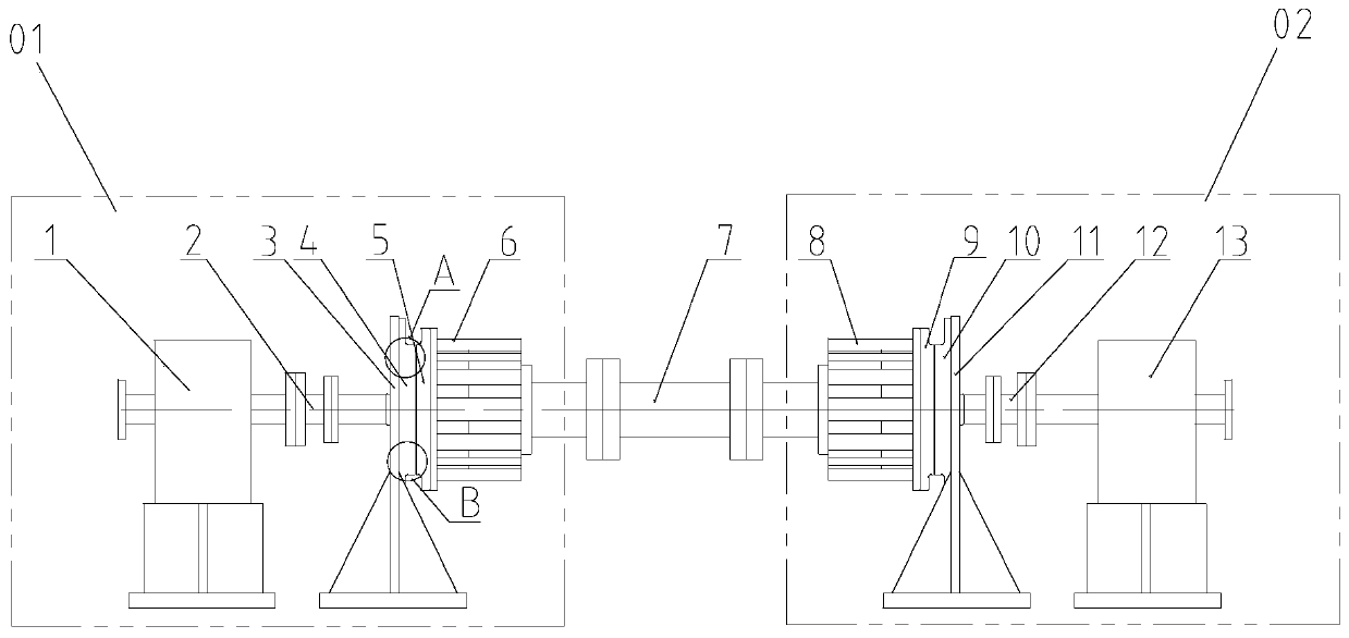
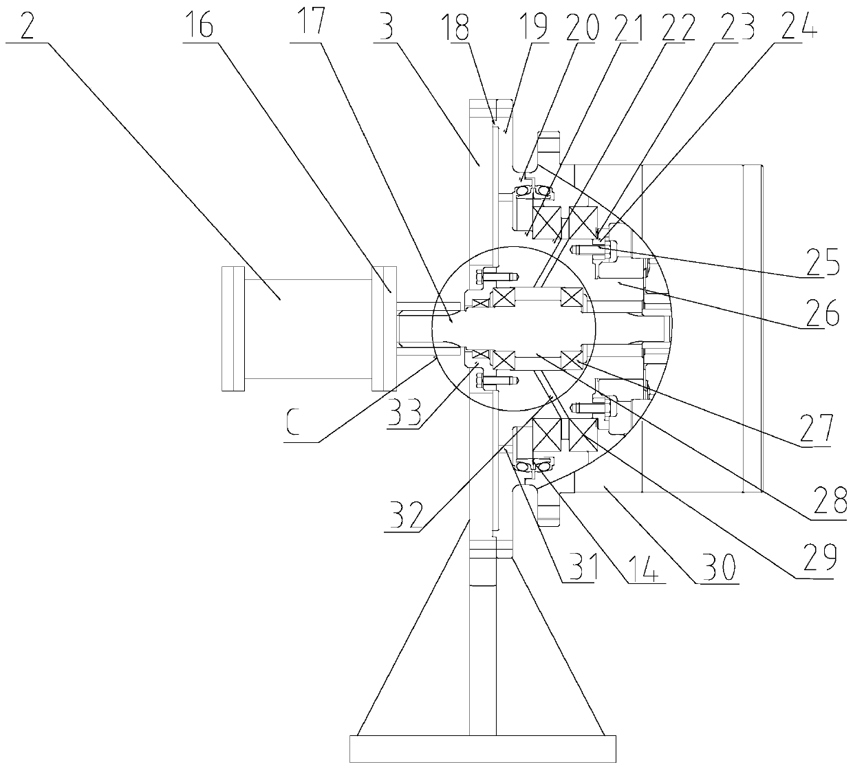
[0029] Such as Figure 1-Figure 5 As shown, the walking speed reducer test system of the present invention includes a test platform (not shown in the figure), a third coupling 7, a main test unit 01 and an accompanying test unit 02; the main test unit 01 and the accompanying test unit 02 pass The third shaft coupling 7 is arranged in a mirror image.

[0030] Among them, the main test unit 01 includes the loading motor 1, the first coupling 2, the first loading tool 4, the main travel reducer 5 to be tested, the first transition connection plate 6, and the first test bench 3; the accompanying test unit 02 It includes a load motor 13, a second coupling 12, a second loading tool 10, a travel reducer 9 to be tested, a second transition connection plate 8, and a second test bench 11;

[0031]The components of the main test unit 01 and th...


PUM


Abstract

The invention provides a travel reducer test system, solving the problem that the existing travel reducer test system is high in cost, large in occupied space and low in efficiency. The test system comprises a test platform, a third coupler, a main test unit and an accompanying test unit; the main test unit and the accompanying test unit are arranged in a mirrored manner via the third coupler; themain test unit comprises a loading motor, a first coupler, a first loading tool, a main travel reducer to be tested and a first transition connection tray connected in sequence; the accompanying testunit comprises a load motor, a second coupler, a second loading tool, an accompanying travel reducer to be tested and a second transition connection tray connected in sequence; the first loading toolis used for achieving dynamic loading performed by the loading motor on the main travel reducer to be tested; the second loading tool is used for achieving dynamic loading performed by the load motoron the accompanying test unit; the loading motor and the load motor are separately connected with the output end and the input end of the test platform, and thus the test platform, the main test unitand the accompanying test unit are formed into a closed loop connection.

Description

technical field [0001] The invention belongs to the field of engineering machinery, and in particular relates to a test system for a traveling reducer. Background technique [0002] The travel reducer is a planetary reduction drive mechanism commonly used in wheeled or crawler machinery. It generally adopts multi-planetary gear transmission. It is an ideal travel drive for crawler engineering vehicles such as road construction machinery, crawler cranes, and excavators. Due to the particularity of the application objects of the travel reducer, it is necessary to conduct product performance tests on the travel reducer, mainly for fatigue operation, overload, and transmission efficiency. [0003] The test system of the travel reducer in the prior art is mainly composed of a test platform (ie console), a hydraulic station, a hydraulic motor, a travel reducer, a dynamometer, a shaft coupling and the like. Among them, the hydraulic station provides high-pressure oil to drive the ...

Claims


Application Information

Patent Timeline
Patent Type & Authority Applications(China)
IPC IPC(8): G01M13/02G01K1/14
CPCG01K1/14G01M13/02
Inventor 杨双虎
Owner SHAANXI FAST AUTO DRIVE GROUP CO LTD
Why Eureka
Try Eureka