Permanent magnet synchronous motor control method based on virtual signal injection and gradient descent method

A technology of permanent magnet synchronous motor and gradient descent method, which is used in motor control, motor generator control, AC motor control, etc.

Active Publication Date: 2019-10-15
ZHEJIANG UNIV
View PDF4 Cites 6 Cited by
  • Summary
  • Abstract
  • Description
  • Claims
  • Application Information

AI Technical Summary

Problems solved by technology

[0005] In order to solve the problems existing in the prior art, the object of the present invention is to provide a maximum torque-to-current ratio and a field-weakening control method of the built-in permanent magnet synchronous motor based on virtual signal injection and gradient descent method, which can be changed in parameters The control of the maximum torque-current ratio can be realized under the condition of the maximum torque-current ratio, and the smooth switching between the maximum torque-current ratio and the field-weakening control can be ensured. Seamless switching between control and field weakening control

Method used


Image

  • Permanent magnet synchronous motor control method based on virtual signal injection and gradient descent method
  • Permanent magnet synchronous motor control method based on virtual signal injection and gradient descent method
  • Permanent magnet synchronous motor control method based on virtual signal injection and gradient descent method

Examples


Embodiment Construction

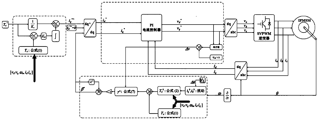
[0044] The technical solution of the present invention is applied to the built-in permanent magnet synchronous motor driven by a two-level three-phase inverter. The overall control block diagram is as follows image 3 shown.

[0045] Embodiments of the present invention and its implementation process are as follows:

[0046] Firstly, the collected stator three-phase current is transformed into the d-q coordinate system of the permanent magnet synchronous motor, and further processed to obtain the actual angle value of the stator current vector;

[0047] Specifically collect the three-phase current of the motor, and obtain the d-q axis component i of the stator current vector through Parker transformation d i q .

[0048] The output of the current PI controller is the reference value of the d-q axis component of the stator voltage vector. Because it is in the linear modulation area and the carrier frequency is relatively high, it can be considered that the actual d-q axis com...


PUM


Abstract

The invention discloses a permanent magnet synchronous motor control method based on a virtual signal injection and gradient descent method. In the real-time control process of a permanent magnet synchronous motor, a virtual signal is injected under a coordinate system, an angle reference value of a stator current vector is obtained by utilizing a virtual signal injection method and a gradient descent method, a reference value of a stator current vector axial component is obtained by adopting a torque compensation calculation method, a stator current vector reference value under a d-q coordinate system is further obtained by coordinate transformation, and a gradient value under the coexistence of the maximum current torque ratio control and weak magnetic control is corrected and controlled, so that seamless switching between the maximum current torque ratio control and the weak magnetic control is achieved. According to the invention, the gradient expression is corrected by introducingvoltage feedback, seamless switching between the maximum current torque ratio control and the weak magnetic control can be achieved, the rotating speed range is wide, complex signal processing is notrequired, and the dynamic response performance is good.

Description

technical field [0001] The invention relates to a control method of a permanent magnet synchronous motor, and in particular proposes a high-efficiency and high-performance control method for a wide speed range of a built-in permanent magnet synchronous motor, which involves the maximum torque-current ratio based on virtual signal injection control and field weakening control. Background technique [0002] Due to the anisotropy of the magnetic circuit, the d-axis and q-axis inductance of the interior permanent magnet synchronous motor are not equal, so the torque of the interior permanent magnet synchronous motor includes two parts: permanent magnet torque and reluctance torque. There is an optimal combination between these two parts, so that the stator current is the smallest under the same torque. This operating state is called the maximum torque current ratio control. When the motor speed is below the base speed, since the copper loss accounts for a large proportion, the ...

Claims


Application Information

Patent Timeline
Patent Type & Authority Applications(China)
IPC IPC(8): H02P21/00H02P25/022
CPCH02P21/0021H02P21/0089H02P25/022H02P2207/05
Inventor 黄晓艳章夏荷
Owner ZHEJIANG UNIV
Why Eureka
Try Eureka