Welding deformation and joint quality control method

A quality control method and welding deformation technology, applied in welding equipment, welding equipment, auxiliary welding equipment, etc., can solve problems such as difficulty in meeting manufacturing requirements, large welding deformation of components, and increasing manufacturing costs, so as to improve welding quality and control welding. Deformation, controlling the effect of temperature gradients

Inactive Publication Date: 2019-10-18
哈尔滨现代焊接技术有限公司
View PDF5 Cites 2 Cited by
  • Summary
  • Abstract
  • Description
  • Claims
  • Application Information

AI Technical Summary

Problems solved by technology

[0002] In the field of major equipment manufacturing, for the welding of metal material components with large format and long welds, due to the limitation of the weight or size of the components, or the limitation of the structure of the welded joints, welding can only be performed on the front side of the weld, and it is difficult to pass through the front and back. The two-sided symmetrical welding method controls the welding deformation, so that the welding deformation of the component is relatively large, and the deformation correction has to be used to meet the manufacturing quality of the component, which greatly improves the manufacturing cost. Some components are even difficult to meet after welding deformation correction. Manufacturing requirements
In addition, for the welding of metal material components with large-scale long weld seams, the components to be welded usually rely on the rigid constraints of welding fixtures to achieve the purpose of controlling welding deformation, but this is extremely easy for welding of some high-strength, crack-sensitive materials. Crack defects

Method used


Image

  • Welding deformation and joint quality control method

Examples


Embodiment 1

[0017] A method for welding deformation and joint quality control, comprising: a welding heat source and a heating heat source, the method comprising the steps of:

[0018] (1) Select the metal material, the thickness of the metal material is ≥ 4mm;

[0019] (2) The heating heat source is located on the back of the weld seam, ahead along the welding direction, and the welding heat source is located on the front of the weld seam. When the distance D between the heating heat source and the heating heat source is within the range of 0-100mm, the effect of controlling welding deformation is the best;

[0020] (3) The type of front welding heat source is determined according to the requirements, and the back heating heat source includes but not limited to high-frequency induction heat source, arc heat source and resistance heat source;

[0021] (4) During the welding process, the front welding heat source is used for welding, and the back heating heat source is used to heat the are...

Embodiment 2

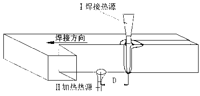
[0024] (1) combine figure 1 The welding deformation and joint quality control method of this embodiment is composed of I welding heat source and II heating heat source. The heating heat source is located on the back of the weld and is in front along the welding direction; the welding heat source is located on the front of the weld, and when the distance D between the welding heat source and the heating heat source is within the range of 0-100mm, the effect of controlling welding deformation is the best.

[0025] (2) combine figure 1 To illustrate this embodiment, during the welding process, the front welding heat source performs welding, and the rear heating heat source heats the area of ​​the weld seam at the front. During welding, the moving speed of the two is the same, and the relative position does not change.

[0026] (3) combine figure 1 To illustrate this embodiment, the welding process parameters of the front welding heat source are determined according to the joint...

Embodiment 3

[0028] Material HQ785 steel, thickness 10mm, plate (weld seam) length 20 meters, plate width 10 meters, butt welding, single-sided single-pass welding. The groove profile adopts Y-shaped butt joint, the blunt edge is 6mm, and the combined groove size is 45°. The welding method adopts laser + MAG composite welding method, and the back heating heat source is in front, which is high-frequency induction heating. Brief welding process parameters are as follows:

[0029] Laser power Kw Current A Welding speed m / min Distance between heating heat source and welding heat source mm Rear heating instant temperature ℃ 8.0 220 1.5 20 400-500

[0030] After welding, the welding deformation is significantly reduced, and the welded joint has no defects such as cracks and pores.


PUM

PropertyMeasurementUnit
thicknessaaaaaaaaaa

Abstract

The invention discloses a welding deformation and joint quality control method. At present, the invention relates to the field of great equipment manufacturing, the welding of the metal material component with the large surface and the long welding line is limited due to the fact that the weight or the size of the component is greatly limited, or is limited by the structural form of a welding joint, so that the problems that the welding deformation of the component is large, and the welding joint easily has defects such as cracks and air holes are solved. According to the welding deformation and joint quality control method, a heating heat source is additionally arranged on the back surface of a welding heat source, the back heating heat source can offset or reduce welding deformation caused in the welding process, meanwhile, the heat source is arranged at the front part of the welding heat source, so that the preheating effect is achieved, welding defects such as cracks, air holes andthe like during welding of high-strength, crack-sensitive materials and thick plate materials can be greatly reduced, so that good welding quality is obtained. The welding deformation and joint quality control method is applied to welding deformation and joint quality control methods.

Description

Technical field: [0001] The invention relates to a method for controlling welding deformation and joint quality. Background technique: [0002] In the field of major equipment manufacturing, for the welding of metal material components with large format and long welds, due to the limitation of the weight or size of the components, or the limitation of the structure of the welded joints, welding can only be performed on the front side of the weld, and it is difficult to pass through the front and back. The two-sided symmetrical welding method controls the welding deformation, which makes the welding deformation of the component larger, and the deformation correction has to be used to meet the manufacturing quality of the component, which greatly increases the manufacturing cost. Some components are even difficult to meet after welding deformation correction. manufacturing requirements. In addition, for the welding of metal material components with large-scale long weld seams...

Claims


Application Information

Patent Timeline
Patent Type & Authority Applications(China)
IPC IPC(8): B23K31/02B23K37/00
CPCB23K31/02B23K37/00
Inventor 王旭友徐良徐富家雷振杨海锋滕彬李荣
Owner 哈尔滨现代焊接技术有限公司
Why Eureka
Try Eureka