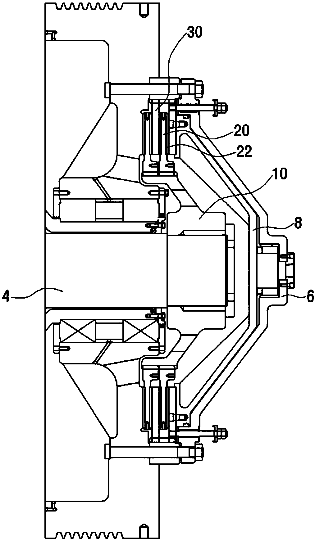
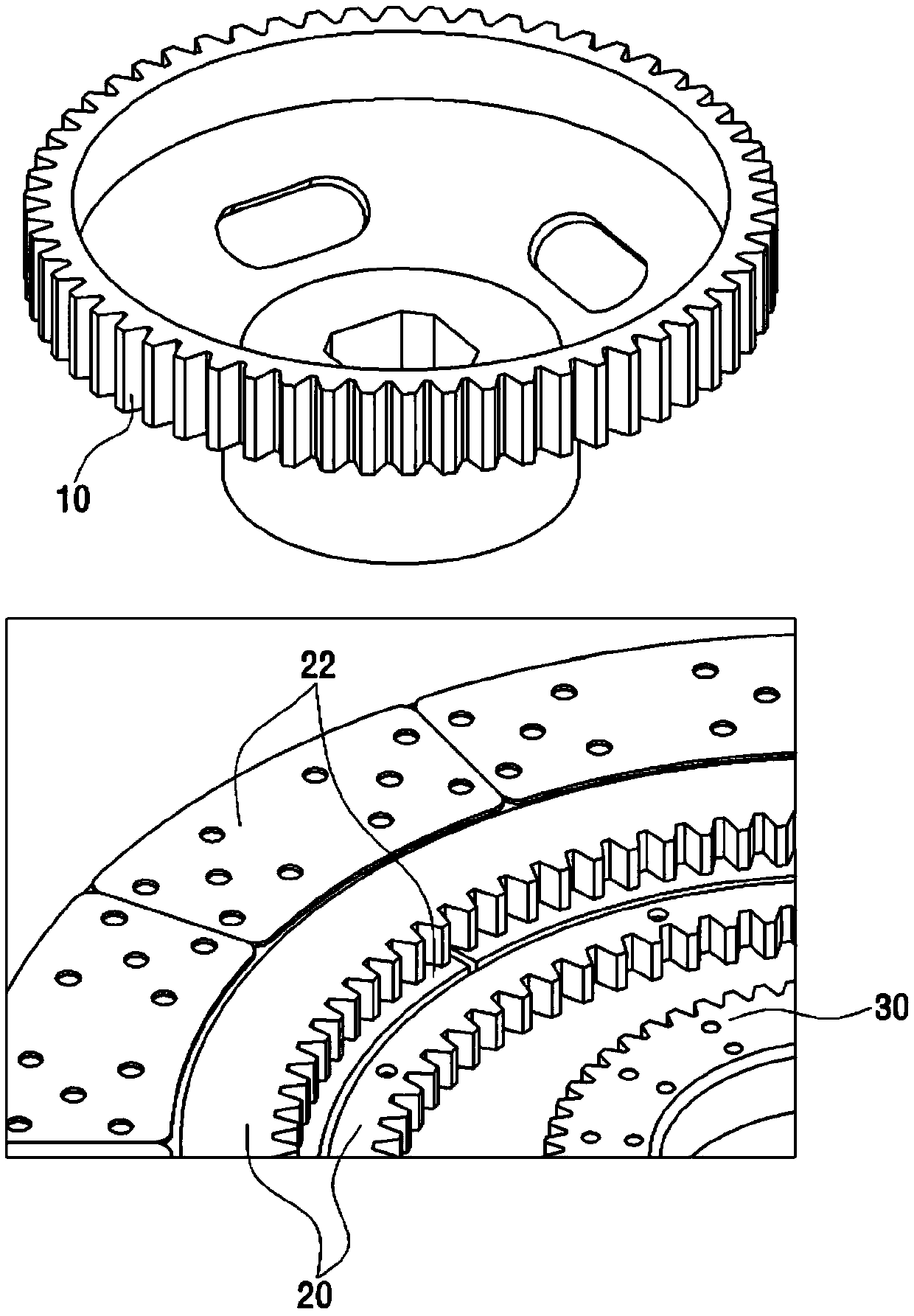
[0051] Next, the structure and effect of the clutch device of the integrated clutch hub for forging press according to the present invention will be described with reference to the drawings.
[0052] For a description of a particular embodiment shown in a drawing, the corresponding drawing is read, and the drawing is considered a part of the description of the entire invention. The mentioned directions or directivity are for convenience of description only, and are not intended to limit the scope of claims of the present invention in any way.
[0053] Specifically, terms showing positions such as "below, above, horizontal, vertical, upper side, lower side, upward, downward, upper, lower", or their derivatives (for example, "in a horizontal direction, downward side, upward "side", etc.), all should refer to the relevant description of the accompanying drawings. In particular, the relative terms are only used for convenience of description, and do not require that the device of the present invention must be configured or act in a specific direction.
[0054] In addition, the words showing the inter-combination relationship between structures such as "installed, attached, connected, connected, and interconnected" are not specifically stated, and refer to individual structures that are directly or indirectly attached or connected or fixed. State, which should be interpreted in terms of attached, connected, and fixed states that can move, and can also be interpreted in terms of states that cannot move.
[0055] When attaching reference signs to components in individual drawings, care should be taken to use the same symbols as much as possible even if the same components are shown in different drawings. In addition, when describing the present invention, specific descriptions of related known configurations or functions are omitted when it is judged that the gist of the present invention is obscured.
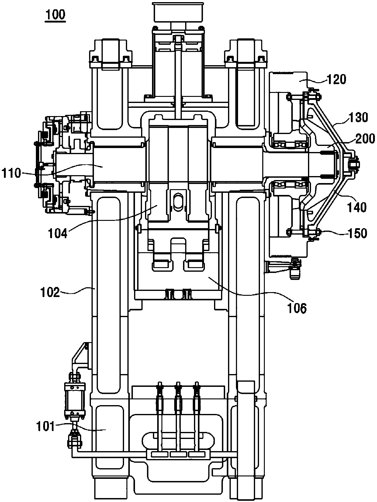
[0056] image 3 It is a sectional view of a forging press according to an embodiment of the present invention, Figure 4 It is a cross-sectional view of a clutch device for a forging press according to an embodiment of the present invention.
[0057] refer to image 3 and Figure 4 , the forging press 100 of the present invention comprises: a machine tool (Bed, 101), which is the spindle bed of the forging press; a frame 102, which is connected with the machine tool 101 to form an overall structure; a crankshaft 110, which runs through the upper end of the forging press 100; a flywheel 120, which The crankshaft 110 connects; the slider 106 performs up and down movement according to the eccentric rotational movement of the connecting rod 104 ; and the clutch device connects or cuts off the rotation of the crankshaft 110 .
[0058] The clutch device includes: a clutch cylinder 130 ; and a clutch piston 140 having a shape corresponding to the clutch cylinder 130 and capable of moving along the crankshaft 110 . The clutch cylinder 130 guides the reciprocating motion of the clutch piston 140 . The connection between the crankshaft 110 and the flywheel 120 is disconnected or connected according to the reciprocating motion of the clutch piston 140 .
[0059] Furthermore, the clutch device includes an integral clutch hub 200 disposed between the flywheel 120 and the clutch piston 140 of the forging press device.
[0060] The one-piece clutch hub 200 replaces the clutch disc and the intermediate pressure plate of the conventional clutch device. For this reason, the integrated clutch hub 200 is an integrated hub in which the main body 210 and the flange part 220 are integrally formed. The flange portion 220 of the one-piece clutch hub 200 performs the functions of a clutch disc and an intermediate pressure plate of a conventional clutch device.
[0061] Clutch slave cylinder 130 and clutch piston 140 are coupled to flywheel 120 via a plurality of clutch bolts 170 . A plurality of clutch bolts 170 pass through the clutch cylinder 130 and the clutch piston 140 to be coupled to the flywheel 120 . Also, the coupling member 180 directly couples the clutch cylinder 130 to the flywheel 120 . Clutch piston 140 is movable between clutch slave cylinder 130 and flywheel 120 .
[0062] Furthermore, the clutch cylinder 130 is connected to the clutch piston 140 through a plurality of guide pins 150 . A plurality of guide pins 150 can guide the movement of the clutch piston 140 .
[0063] Figure 5 A drawing showing a clutch bolt and a guide pin according to an embodiment of the present invention, Image 6 (a) for along Figure 5 The sectional view of the clutch device of the forging machine with an integral clutch hub of the line XX' section, Image 6 (b) for along Figure 5 The line Y-Y' section is a sectional view of the clutch device of the forging machine with an integrated clutch hub.
[0064] and, Figure 7 It is a perspective view of a clutch device of an integrated clutch hub for a forging machine provided with a guide pin according to an embodiment of the present invention. Figure 8 It is a perspective view of a clutch device of an integrated clutch hub for a forging machine provided with a clutch bolt according to an embodiment of the present invention.
[0065] First, refer to Figure 5 and Image 6 , the clutch piston 140 is movable between the clutch slave cylinder 130 and the flywheel 120 . The guide pin 150 is fixedly coupled with the clutch piston 140 at one end. Also, the guide pin 150 is slidably coupled to the clutch piston 130 .
[0066] refer to Figure 5 The clutch slave cylinder 130 has a trapezoidal cylindrical body and an edge portion extending from the outer periphery of the cylindrical body. A plurality of guide pins 150 are provided at an edge portion of the clutch cylinder 130 . Similarly, a plurality of clutch bolts 170 are also provided at the edge portion of the clutch cylinder 130 .
[0067] The edge portion of the clutch cylinder 130 is provided with a plurality of guide pins 150 and has a plurality of first holes 132 formed at regular intervals. The plurality of clutch bolts 170 are provided in the plurality of second holes 134 formed in the peripheral portion of the clutch cylinder 130 . A plurality of first holes 132 and a plurality of second holes 134 are alternately formed along the edge of the clutch cylinder 130 .
[0068] refer to Image 6 (a) and Figure 7 , one end of the guide pin 150 is fixed to the clutch piston 140 through a threaded tap joint 156, and the other end is combined with a clutch spring 154 and a support portion 153 supporting the clutch spring 154 at the clutch cylinder 130, thus, it is linked with the movement of the clutch piston 140 .
[0069] The two guide pins 150 are connected to each other by a safety strip 160 . Due to the repeated piston action of the clutch piston 140 , the clutch spring 154 of the guide pin 150 is ejected from the guide pin 150 to cause danger. For the situation that any spring 154 in the two guide pins 150 pops out, the safety bar 160 prevents the spring 154 from popping out and causing danger. .
[0070] The clutch piston 140 is able to slide on the guide pin 150 . The clutch piston 140 is fixedly coupled to one end of the guide pin 150 . Therefore, when the air pressure or the hydraulic pressure is applied between the clutch cylinder 130 and the clutch piston 140 , the clutch piston 140 moves toward the clutch hub 200 by the air pressure or the hydraulic pressure. The clutch piston 140 is fixedly combined with the guide pin 150 , and when the clutch piston 140 moves, the guide pin 150 is pulled toward the clutch hub 200 to compress the clutch spring 154 .
[0071] Thereafter, when the air pressure or hydraulic pressure between clutch cylinder 130 and clutch piston 140 is removed, clutch spring 154 returns to pull clutch piston 140 toward clutch cylinder 130 . Thus, the clutch piston 140 is easily separated from the clutch hub 200 .
[0072] refer to Image 6 (b) and Figure 8 , a plurality of clutch bolts 170 couple the clutch cylinder 130 with the clutch piston 140 with the flywheel 120 .
[0073] The clutch bolt 170 passes through the clutch piston 140 to couple the clutch cylinder 130 to the flywheel 120 . Specifically, the clutch bolt 170 is fixed to the clutch cylinder 130 at one end and to the flywheel 120 at the other end. The clutch bolt 170 includes a first coupling portion 172 coupled to the clutch cylinder 130 and a second coupling portion 176 coupled to the flywheel 120 .
[0074] Furthermore, the clutch bolt 170 penetrates the clutch piston 140 . Also, the clutch bolt 170 penetrates through the edge of the clutch piston 140 . Clutch piston 140 has a plurality of through holes through which clutch bolts 170 pass. The clutch bolt 170 also includes a retaining ring 174 located in the throughbore of the clutch piston 140 . The snap ring 174 supports the clutch bolt 170 in the through hole of the clutch piston 140 .
[0075] One end of the guide pin 150 can be slidably combined with the clutch cylinder 130 , and the other end of the guide pin 150 is fixedly combined with the flywheel 120 . Also, the guide pin 150 is fixedly combined with the clutch piston 140 . Accordingly, when air pressure or hydraulic pressure is applied between the clutch cylinder 130 and the clutch piston 140 , the clutch cylinder 130 slides along the guide pin 150 .
[0076] Below, refer to Figure 9 to Figure 11 , the integrated clutch hub 200 will be described.
[0077] Figure 9 is a perspective view of an integrated clutch hub according to an embodiment of the present invention, Figure 10 A front view and a perspective view of a one-piece clutch hub to which a block liner is mounted according to an embodiment of the present invention.
[0078] refer to Figure 9 and Figure 10 , the one-piece clutch hub 200 includes: a main body 210, which has a hollow portion 202 for inserting the crankshaft 110; a flange portion 220, which is formed by extending radially from the edge of the main body 210 and has a plurality of openings 212; and a plurality of block-shaped gaskets 222 , installed in the plurality of openings 212 of the flange part 220 .
[0079] The body 210 of the one-piece clutch hub 200 includes a hub 206 having a hollow portion 202 into which the crankshaft 110 is inserted, and a connecting portion 208 connecting the hub 206 and a flange portion 220 . The hub 206 has a cylinder shape. The connecting portion 208 is formed obliquely from the edge of one end of the hub 206 to the flange portion 220 . The connecting portion 208 has a trapezoidal cylinder shape.
[0080] The flange portion 220 is formed by extending the edge of the connecting portion 208 substantially perpendicular to the axis of the hub 206 . The flange portion 220 corresponds to a clutch disc or an intermediate pressure plate of a conventional clutch device. Since the flange portion 220 is extended from the trapezoidal cylinder-shaped connecting portion 208 , it has a roughly donut shape.
[0081] The plurality of openings 212 are spaced apart at predetermined intervals in the circumferential direction on the flange portion 220 . The block spacers are respectively inserted into the plurality of openings 212 in a block shape. The block pad 222 has a trapezoidal shape. The present invention is not limited to the case where the block liner 222 has a trapezoidal shape, and the block liner 222 can be any shape that is obvious to those skilled in the art.
[0082] The block packing 222 has the same thickness as the flange part 220 or has a greater thickness. When the one-piece clutch hub 200 is mounted on the press machine 100, the block gasket 222 inserted into the flange part 220 of the one-piece clutch hub 200 is located between the outer peripheral end of the clutch piston 140 and the flywheel 120, and can transmit the friction due to friction. power generated by force. When the thickness of the block packing 222 is greater than that of the flange portion 220 , the flywheel 120 and the clutch piston 140 are not in contact with the flange portion 220 of the one-piece clutch hub 200 but are in contact with the thick block packing 222 . Accordingly, power generated by friction can be transmitted without damaging the integrated clutch hub 200 .
[0083] The block packing 222 is detachable through the opening 212 . Therefore, for the case where a specific block packing 222 is worn out, the worn block packing 222 among the plurality of block packings 222 installed in the plurality of openings 212 of the flange portion 220 is removed, after the removed block packing 222 is removed. By inserting a new block packing 222 into the opening 212 of the worn block packing 222, the block packing can be easily replaced. The crankshaft 110 is inserted into the hollow portion 202 of the main body 210 . In other words, the crankshaft 110 is coupled to the hollow portion 202 of the hub 206 .
[0084] Crankshaft 110 is coupled to hub 206 by a shrink fit. The hollow portion 202 of the hub 206 has an inner diameter slightly smaller than the outer diameter of the crankshaft 110 . When the crankshaft 110 and the hub 206 are coupled by interference fitting, the crankshaft 110 is interference-fitted after the hub 206 is heated and expanded, whereby the crankshaft 110 and the hub 206 can be adhered and tightly coupled.
[0085] Figure 11 It is a front view of the hub of the main body of the integrated clutch hub according to an embodiment of the present invention.
[0086] A plurality of keys (not shown) are arranged between the crankshaft 110 and the hub 206 to securely couple the crankshaft 110 and the hub 206 . In terms of the characteristics of the forging press, the one-piece clutch hub 200 receives relatively large forces. As a result, the coupling between the integrated clutch hub 200 and the crankshaft 110 becomes loose. In order to prevent this, after the crankshaft 110 and the hub 206 are coupled by interference fit, a plurality of keys are inserted between the crankshaft 110 and the hub 206 .
[0087] The keys are arranged at regular intervals along the inner peripheral surface of the hub 206 . To this end, the inner peripheral surface of the hub 206 has a plurality of grooves (204) in which a plurality of keys are arranged. A plurality of keys are cylinder keys. It contains taper pins inside.
[0088]After the cylinder key is arranged between the crankshaft 110 and the hub 206, the taper pin inside the cylinder key is pulled to expand the cylinder key. For this case, the crankshaft 110 and the hub 206 can be more positively fixed to each other.
[0089] Integral Clutch Hub 200, again see Figure 9 and Figure 10 , the one-piece clutch hub 200 is integrally formed with a main body 210 connected to the crankshaft 110 and a flange portion 220 capable of detachable block gaskets. The necessity of a clutch disc and an intermediate pressure plate installed for power transmission. Furthermore, the one-piece clutch hub 200 eliminates the necessity of a plurality of clutch discs and intermediate pressure plates, thereby reducing gaps (gaps) between components.
[0090] The operation of the clutch will be described. When the clutch piston 140 is in operation, the block gasket 222 mounted on the integrated clutch hub 200 is pressed between the clutch piston 140 and the flywheel 120, thereby constituting power transmission.
[0091] Specifically, the outer peripheral end of the clutch piston 140 moves the integrated clutch hub 200 toward the flywheel 120 along the crankshaft 110 , thereby pressing the block gasket 222 mounted on the integrated clutch hub 200 and the flywheel 120 to make the crankshaft 110 move toward the flywheel 120 . The rotational power is transmitted to the flywheel 120.
[0092] The flange portion 220 of the one-piece clutch hub 200 has a plurality of block gaskets 222 attached to the plurality of openings 212 , so that the one-piece clutch hub 200 can transmit power between the clutch piston 140 and the flywheel 120 .
[0093] In the clutch device of the one-piece clutch hub for forging press according to the embodiment of the present invention constituted as described above, when the specific block packing 222 is worn, the plurality of openings 212 attached to the flange 220 are removed. The worn block liner 222 in each block liner 222 is removed, and a new block liner 222 is inserted into the opening 212 from which the worn block liner 222 has been removed. Therefore, it is easy to replace the block liner 222. .
[0094] In addition, in the clutch device of the integrated clutch hub for forging presses according to the embodiment of the present invention, the necessity of a plurality of clutch discs and intermediate pressure plates in the conventional clutch device is eliminated, thereby reducing the gap (gap) between parts. ). In other words, in the clutch device of the one-piece clutch hub for forging presses according to the embodiment of the present invention, the one-piece clutch hub 200 performs the functions of the clutch disc and the intermediate pressure plate, whereby the gap between the parts is smaller than that of the conventional clutch device. gap.
[0095] Furthermore, in the clutch device of the integrated clutch hub for forging press according to the embodiment of the present invention, since the number of consumable parts is less than that of the conventional clutch device, maintenance and management of the clutch device are easy.
[0096] Although the present invention specifically described above has been described on the basis of the limited embodiments and accompanying drawings, the present invention is not limited thereto, and those of ordinary skill in the technical field of the present invention can understand the technical ideas and claims of the present invention Various corrections and modifications are made within the same range as the range.
[0097] However, it should be understood that simple amendments and deformations thereof do not depart from the scope of rights of the present invention.