Rubber roller

A rubber roller and rubber technology, which is applied in the field of rubber rollers, can solve the problems affecting the service life and the production quality of composite films, and achieve the effect of reducing the processing quality

Pending Publication Date: 2019-10-22
周宇凡
View PDF13 Cites 1 Cited by
  • Summary
  • Abstract
  • Description
  • Claims
  • Application Information

AI Technical Summary

Problems solved by technology

[0004] In order to make up for the deficiencies of the prior art, the invention proposes a rubber roller. The invention is mainly used to solve the problem that a large amount of static electricity will be generated due to the mechanical friction between the production raw materials and the rubber roller. , static electricity will generate sparks on the outer surface of the rubber roller when it is released, and the rubber roller will affect the service life after a long time of work; at the same time, the generated electric spark will affect the production quality of the composite film

Method used


Image

  • Rubber roller
  • Rubber roller
  • Rubber roller

Examples


Embodiment Construction

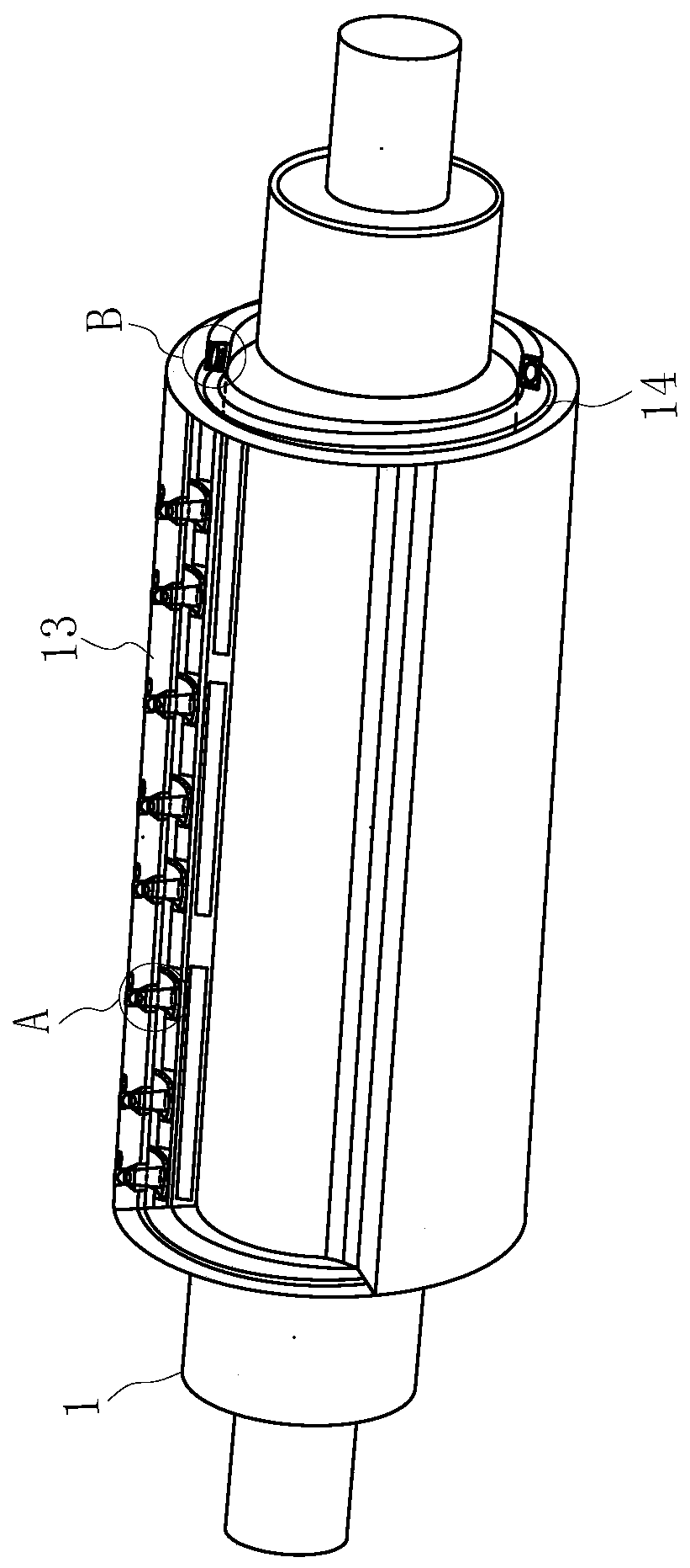
[0021] use Figure 1-Figure 5 A rubber roller according to one embodiment of the present invention will be described below.

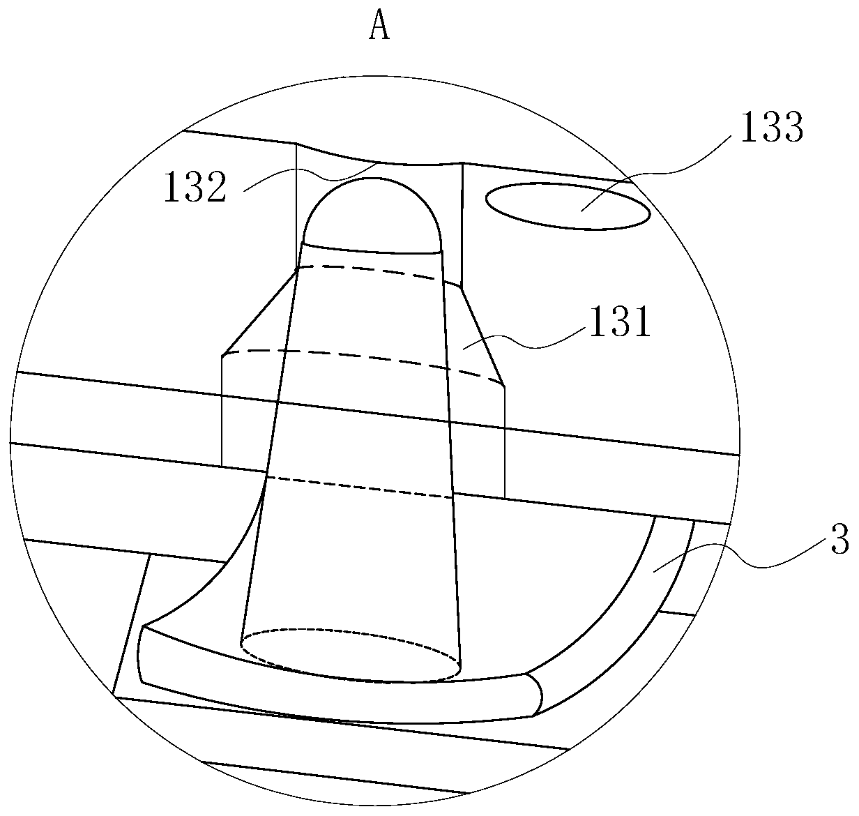
[0022] Such as Figure 1-Figure 5As shown, a rubber roller according to the present invention includes a rotating main roller 1, a rubber base layer 11 and a glass fiber layer 12; the outer wall of the rotating main roller 1 is provided with a rubber base layer 11, and the outer wall of the rubber base layer 11 A glass fiber layer 12 is arranged on it; an insulating cavity 121 is opened inside the glass fiber layer 12, and an elastic wear-resistant layer 13 is arranged on the outer wall of the glass fiber layer 12; an elastic metal mesh 2 is arranged in the insulating cavity 121; The elastic wear-resistant layer 13 is uniformly provided with stepped holes 131, and the diameters of the stepped holes 131 increase sequentially from top to bottom; It communicates with the insulating cavity 121; the bottom of the insulating cavity 121 is provided with an e...


PUM


Abstract

The invention belongs to the technical field of rubber rollers, and in particular relates to a rubber roller. The rubber roller comprises a rotating main roller, a rubber base layer and a glass fiberlayer. An insulating cavity is formed in the glass fiber layer, and an elastic anti-wear layer is arranged on the outer wall of the glass fiber layer; step holes are uniformly formed in the elastic anti-wear hole, and sunken grooves are formed in the top ends of the step holes; an elastic concave film plate is arranged at the bottom of the insulating cavity, cone-shaped ejector pins are arranged above the elastic concave film plate, and the cone-shaped ejector pins penetrate mesh holes of an elastic metal screen; electricity gathering balls are arranged at the top ends of the cone-shaped ejector pins and are located in the step holes; an expansion cavity is formed in an arc-shaped concave plate; an extrusion cavity is formed in the side wall of each step hole, and the extrusion cavity communicates to the expansion cavity through a gas vent. The condition that the service life of the rubber roller is affected as sparks are generated on the rubber roller because static electricity is generated by mechanical friction between a composite film and the rubber roller and a long-time collective phenomenon is generated on the outer wall of the rubber roller is prevented effectively.

Description

technical field [0001] The invention belongs to the technical field of rubber rollers, in particular to a rubber roller. Background technique [0002] Rubber roller is a roller-shaped product made of metal or other materials as the core and covered with rubber after vulcanization. It is widely used in papermaking industry, printing and dyeing industry, textile industry, printing industry, grain processing, metallurgical industry, plastic Processing, packaging machinery and other industries. [0003] Coating laminating machine is used in the production process of aluminum foil cellophane polyamide, polyethylene, polypropylene and other composite films with smooth surface, and the composite film is prone to static electricity during the transmission process between the drive rollers; especially in the coating laminating machine During the winding process, due to the mechanical friction between the raw materials and the rubber roller, a large amount of static electricity will ...

Claims


Application Information

Patent Timeline
Patent Type & Authority Applications(China)
IPC IPC(8): B65H20/02B65H27/00
CPCB65H20/02B65H27/00B65H2301/5133B65H2401/111B65H2404/19
Inventor 周宇凡周世宇齐鹏
Owner 周宇凡
Why Eureka
Try Eureka