
Sliding main bearing drive chain and wind turbine including same

A transmission chain and main bearing technology, applied in sliding contact bearings, wind turbines, bearings in rotary motion, etc., can solve the problems of unstable and reliable work, short bearing service life, long production cycle, etc., to shorten production cycle, shock resistance Good performance and long service life

Active Publication Date: 2021-03-26
SHANGHAI ELECTRIC WIND POWER GRP CO LTD
View PDF7 Cites 0 Cited by
  • Summary
  • Abstract
  • Description
  • Claims
  • Application Information

AI Technical Summary

Problems solved by technology

[0004] The technical problem to be solved by the present invention is to overcome the low bearing capacity of the rolling main bearing of the wind turbine in the prior art, poor shock resistance, not stable and reliable work, not easy to manufacture, long production cycle, high production cost, and impossible maintenance. Short service life defect, providing a sliding main bearing transmission chain and a wind turbine including the same

Method used


Image

  • Sliding main bearing drive chain and wind turbine including same
  • Sliding main bearing drive chain and wind turbine including same
  • Sliding main bearing drive chain and wind turbine including same

Examples


Embodiment 1

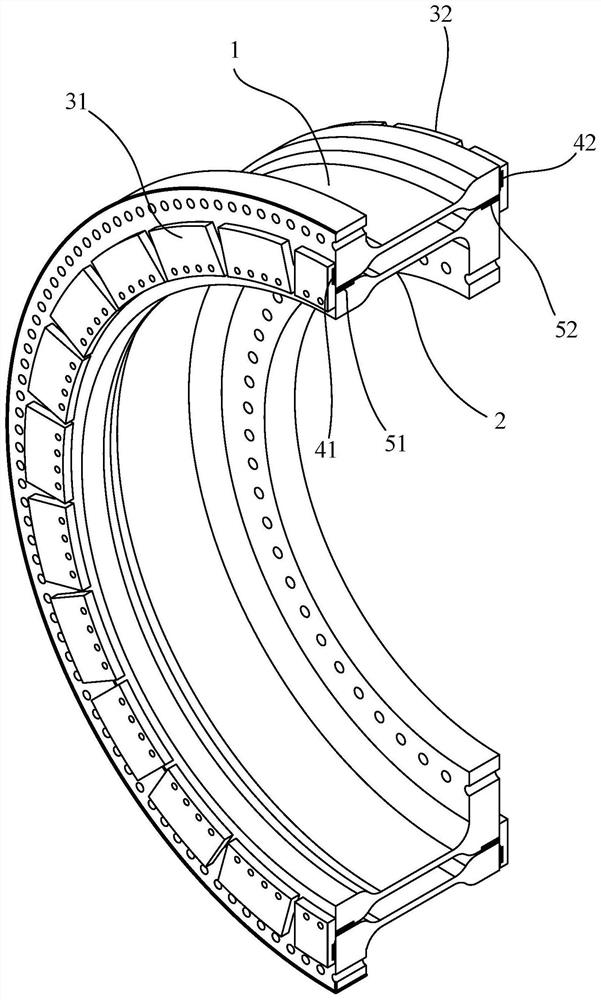
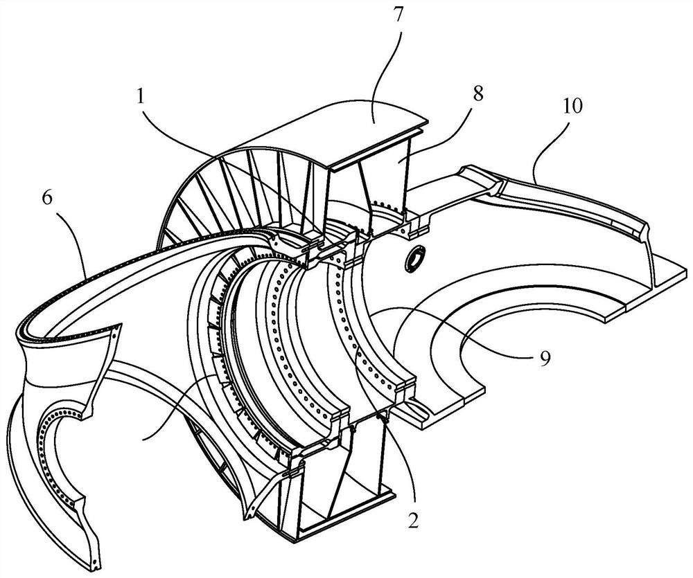
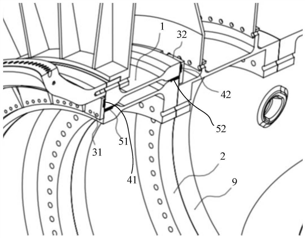
[0037] Such as Figure 1-Figure 3 As shown, this embodiment discloses a sliding main bearing transmission chain, wherein the sliding main bearing transmission chain of this embodiment includes a bearing outer ring 1, a bearing inner ring 2, an end pressure plate 31 and an end surface pressure plate 32, and an axial slider 41 and axial slider 42, radial slider 51 and radial slider 52, hub 6, generator rotor 7, generator stator 8, fixed shaft 9, main base 10.

[0038] Such as Figure 1-Figure 3 As shown, the sliding main bearing transmission chain of this embodiment includes a bearing inner ring 2 and a bearing outer ring 1 . Wherein, the bearing outer ring 1 is arranged on the outer side of the bearing inner ring 2 in the radial direction, and the two are arranged in parallel.

[0039] Such as figure 1 and image 3 As shown, the transmission chain of the sliding main bearing in this embodiment includes two sets of end face pressure plates (end face pressure plate 31 and end...

Embodiment 2

[0061] Such as Figure 4 and Figure 5 As shown, this embodiment discloses a sliding main bearing transmission chain, wherein, the bearing outer ring 1, the bearing inner ring 2, the end surface pressing plate 31 and the end surface pressing plate 32, and the axial slider of the sliding main bearing transmission chain in this embodiment 41, axial slider 42, radial slider 51, and radial slider 52 are all the same as in Embodiment 1, and will not be repeated here.

[0062] In this embodiment, the bearing inner ring 2 is connected to the generator rotor 7 and the hub 6 . In the way of inner ring rotation, the load acting point is located outside the two groups of radial sliders (radial slider 51 and radial slider 52 ), which has a relatively large bending moment load.

[0063] Such as Figure 4 and Figure 5 As shown, the generator rotor 7 of this embodiment is arranged on the outer side of the bearing outer ring 1 in the radial direction, and the bearing inner ring 2 has a c...


PUM


Abstract

The invention discloses a sliding main bearing transmission chain and a wind turbine comprising the same. The sliding main bearing transmission chain comprises a bearing inner ring, a bearing outer ring, end surface pressing plates, two groups of axial sliding blocks and two groups of radial sliding blocks, wherein the two groups of axial sliding blocks are used for providing static-dynamic friction isolation and load transmission between the bearing inner ring / the bearing outer ring and the end surface pressing plates on the two sides, the two groups of radial sliding blocks are used for providing static-dynamic friction isolation and load transmission between the bearing inner ring and the bearing outer ring, and the two groups of radial sliding blocks are arranged at intervals in the axial direction. Compared with a rolling main bearing, the sliding main bearing transmission chain has the advantages that the bearing capacity is larger, the shock resistance is good, stable and reliable working is realized, the reliability of a fan is improved, manufacturing is easy, the production period is shortened, and the production cost is reduced; the end surface pressing plates are detachable, the axial sliding blocks and the radial sliding blocks can be replaced, and the service life of a bearing is long; and meanwhile, compared with a three-point contact sliding bearing, the frictionforce is reduced, so that the heating amount and the abrasion amount are reduced.

Description

technical field [0001] The invention relates to a sliding main bearing drive chain and a wind turbine comprising the same. Background technique [0002] Currently there is a direct drive drive train structure for wind turbines. This kind of transmission chain structure generally adopts the form of rolling main bearing. Such as a single double-row tapered roller bearing or two single-row tapered roller drive chains. The rolling main bearing of the transmission chain directly driven by the wind turbine has low load capacity, poor shock resistance, not stable and reliable work, not easy to manufacture, long production cycle, high production cost, impossible to maintain, and short service life of the bearing. [0003] At present, there are also wind turbines using sliding bearing technology, but the general maintainability is not high. Because sliding bearings have the disadvantages of greater heat generation and faster wear than rolling bearings. Contents of the invention ...

Claims


Application Information

Patent Timeline
Patent Type & Authority Patents(China)
IPC IPC(8): F03D80/70F03D80/00F16C17/10F16C33/04
CPCF16C17/10F16C33/04F03D80/00F03D80/70Y02E10/72Y02P70/50
Inventor 曹李兴
Owner SHANGHAI ELECTRIC WIND POWER GRP CO LTD
Learn More