
Stepless transmission of hydraulic machinery

A technology of continuously variable transmission and hydraulic machinery, which is applied in the direction of mechanical equipment, fluid transmission devices, belts/chains/gears, etc., can solve the problems of uncompact gearbox structure, low transmission reliability, and difficult installation, etc., and achieve reduction The size of the gearbox, the ease of operation, and the effect of improving transmission efficiency

Pending Publication Date: 2019-10-22
JIANGSU POLYTECHNIC COLLEGE OF AGRI & FORESTRY
View PDF1 Cites 11 Cited by
  • Summary
  • Abstract
  • Description
  • Claims
  • Application Information

AI Technical Summary

Problems solved by technology

[0003] Chinese Invention Patent Publication No.: CN204647180U, Name: A hydraulic-mechanical continuously variable transmission for high-power tractors. The hydraulic-mechanical continuously variable transmission proposed in this patent is composed of three basic components: a variable pump, a quantitative motor, and a planetary busbar. The power input The shaft and the power output shaft are on the same axis. When the tractor is running or parking, the PTO output can be realized by independently operating the action of the double-acting clutch; the output of the tractor power is the hydraulic power and mechanical power of the bus through the front planetary row. It is realized after converging with the rear planetary row. At the same time, there are four working sections connected head-to-tail, and all of them are in the form of output after the confluence of hydraulic flow and mechanical flow. A forward / reverse synchronizer is installed at the left end of the mechanical power input shaft of the confluence row. The function is realized by the synchronous action of this synchronizer and a pair of fixed-shaft meshing gears with an idler structure, which makes the structure of the gearbox not compact and difficult to install
[0004] The hydromechanical continuously variable transmission proposed at present has both multi-planetary confluence design and single planetary confluence design. In the design of the reverse gear, a synchronizer and a pair of constant meshing fixed-axis gear pairs are mostly used to realize it, so that The gearbox has problems such as uncompact structure, low transmission reliability, high noise, and difficult installation

Method used


Image

  • Stepless transmission of hydraulic machinery

Examples


Embodiment Construction

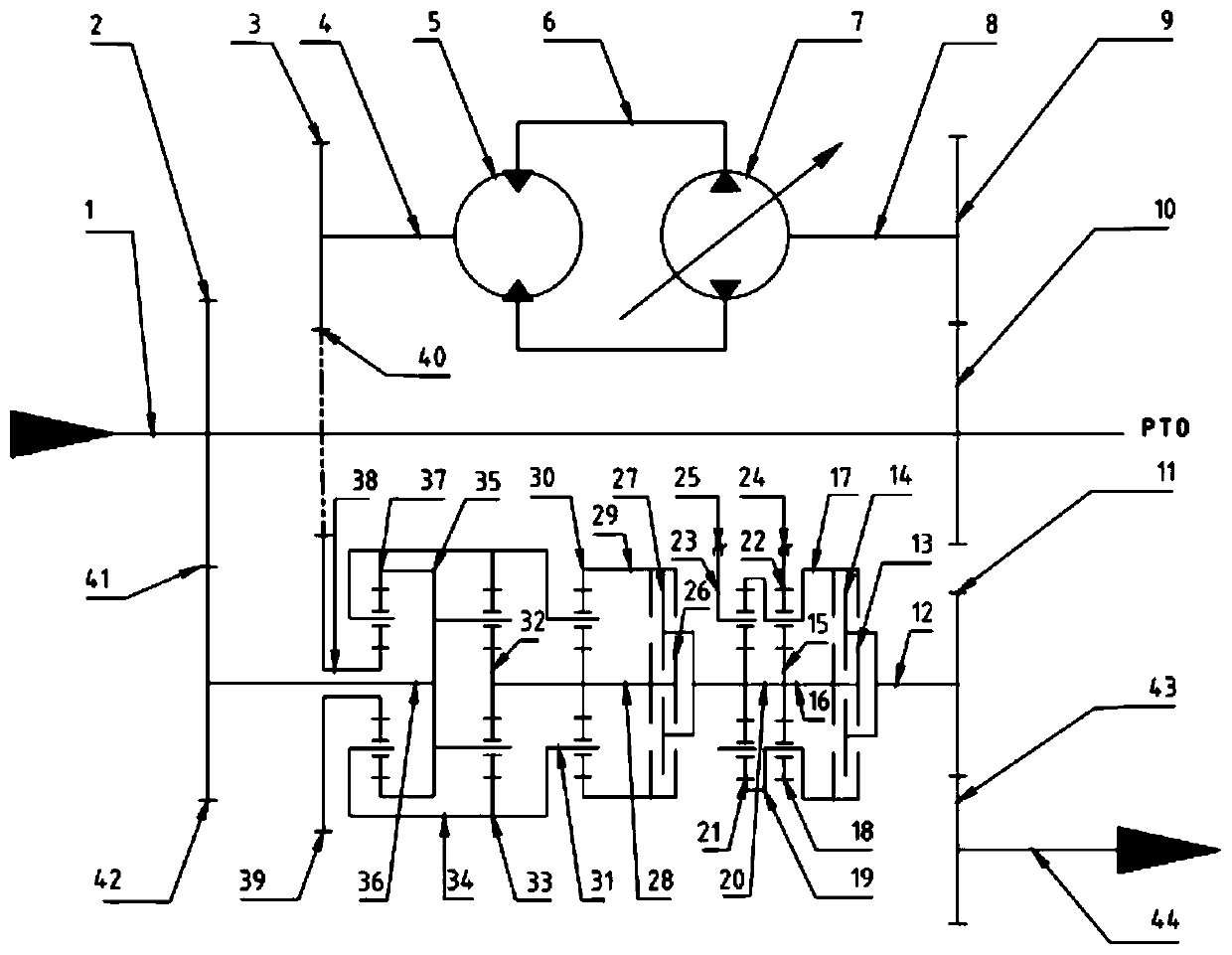
[0013] Such as figure 1 As shown, a hydraulic mechanical continuously variable transmission of the present invention includes a power input shaft 1, a pump-controlled hydraulic motor system 6, a confluence planetary row mechanism, a double planetary gear reversing mechanism 20, and a power output shaft 44, and the power input shaft 1 The power input shaft gear II10 is connected to one end of the pump control hydraulic motor system 6, and the other end of the pump control hydraulic motor system 6 is connected to the confluence planetary row mechanism through the hydraulic power distribution gear pair 40, and the confluence planetary row mechanism passes through the reversing planetary row The common sun gear shaft 16 is connected to the double planetary gear reversing mechanism 20, and the double planetary gear reversing mechanism 20 is connected to the power output shaft 44, and the right end of the power input shaft 1 is directly used as a PTO to output the engine power, which...


PUM


Abstract

The invention discloses a stepless transmission of hydraulic machinery. The stepless transmission comprises a power input shaft, a pump controlled hydraulic motor system, a bus planetary row mechanism, a duplex planetary gear reversing mechanism and a power output shaft. A brake installed in the duplex planetary gear reversing mechanism is independently controlled, so that two working modes of forward and backward movement of a tractor can be selected, and multi-section continuous stepless speed control output of power of the tractor is realized. The transmission has the advantages of the compact structure, reasonable design, convenience in operation and high transmission efficiency and has high economic benefits.

Description

technical field [0001] The invention relates to the field of hydraulic mechanical transmission, in particular to a hydraulic mechanical continuously variable transmission. Background technique [0002] Tractor is an important agricultural production machinery and vehicle. It has to complete a variety of operations, the working environment is harsh, and the external load changes frequently. The intelligent high-horsepower tractor can change the transmission ratio of the gearbox in real time according to the change of the external load to adapt to the load. The torque and speed changes caused by the changes have great development prospects. The use of hydraulic-mechanical continuously variable transmissions on intelligent high-horsepower tractors can combine the adjustable hydraulic transmission speed ratio with the high efficiency of mechanical transmission, which can not only improve the handling stability and driving comfort of the tractor, but also improve the power and pe...

Claims


Application Information

Patent Timeline
Patent Type & Authority Applications(China)
IPC IPC(8): F16H47/04
CPCF16H47/04
Inventor 王家博高菊玲李东洋钟兴张海军肖茂华王光明胡玉婷
Owner JIANGSU POLYTECHNIC COLLEGE OF AGRI & FORESTRY
Learn More