

Gas liquid supercharging power generator
A technology of power generation device and gas-liquid booster, which is applied to electromechanical devices, safety devices, electrical components, etc., can solve the problems of distribution limitation, difficult power supply mode, and large seasonal influence, and achieve the effect of low power generation cost
- Summary
- Abstract
- Description
- Claims
- Application Information
AI Technical Summary
Problems solved by technology
Method used
Image

Examples
Embodiment 1
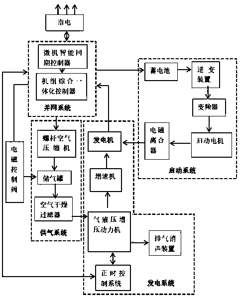
[0121] The three-cylinder gas-hydraulic supercharged power generation power plant is used for illustration:
[0122] Such as Figures 1 to 8 As shown, taking a 100-kilowatt generator driven by it as an example, the total length of the crankshaft of the gas-hydraulic booster power machine is 1220mm, the piston rod is 40mm, the total length of the connecting rod is 320mm, the stroke is 65mm, and its rated speed is 500 rpm. A speed-up gearbox is connected in front of the generator, and the low-speed shaft speed of the gearbox is 25 revolutions per minute to ensure that the generator reaches the rated speed to generate electricity normally. Its torque can be calculated. Motor torque (Nm) T=K(9550)×P(Kw) / n (number of revolutions r / min) is equal to 18718Nm / meter, motor input torque×speed ratio=411796Nm / meter= Gearbox input torque = crankshaft output torque ÷ trigonometric function of crankshaft turnover. (Crankshaft stroke turnover radius is 65mm)=74872Nm Nm / m÷9.8=7640Kg / m=Pneumat...
Embodiment 2
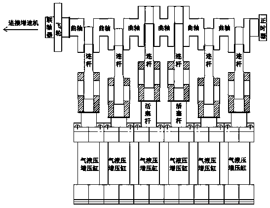
[0124] Take a six-cylinder gas-hydraulic supercharged power machine for illustration:
[0125] Such as Figure 1 to Figure 8 As shown, each constituent unit or part of the six-cylinder gas-hydraulic supercharged power machine is basically the same as that of the three-cylinder gas-hydraulic supercharged power machine. The difference is that the piston rod, connecting rod, and crankshaft of the air-hydraulic booster cylinder, which are the components of the air-hydraulic booster power machine, have different lengths and combinations. The six-cylinder air-hydraulic booster cylinder, connecting rod, and crankshaft are combined in three groups. The first group is 1-6, the second group is 2-5, and the third group is 3-4.
[0126] Take it to drive a generator with a rated speed of 500 rpm and a rated power of 500kw as an example: the total length of the crankshaft of the gas-hydraulic booster power machine is 1450mm, the piston rod is 60mm, the stroke is 65mm, the total length of t...
PUM
 Abstract
Description
Claims
Application Information