Flotation column device

A flotation column and cylindrical section technology, which is applied in flotation, solid separation and other directions, can solve the problems of high column height and negative impact on the flow field at the upper end of the column, so as to achieve a small footprint and reduce the desorption of coarse particles. , the effect of improving the sorting efficiency

Active Publication Date: 2019-10-25
CENT SOUTH UNIV
View PDF9 Cites 3 Cited by
  • Summary
  • Abstract
  • Description
  • Claims
  • Application Information

AI Technical Summary

Problems solved by technology

[0006] Similarly, the Chinese Utility Model Patent Application No. 201720642570.X discloses a variable-diameter flotation column with fillers, which is composed of multi-section flotation columns with gradually reduced diameters from top to bottom. The two adjacent subsection flotation columns are connected by variable diameter sections, and the sweeping section, rough selection section and fine selection section can be realized in one flotation column, but, similarly, the The device is a static flotation column type device, and the height of the column is relatively high
[0007] The existing jet flotation columns are all straight cylinders. When the turbulent flow at the lower end of the column is high, it is beneficial to the collision and adhesion of particles and bubbles, but it will also have a certain negative impact on the flow field at the upper end of the column.

Method used


Image

  • Flotation column device
  • Flotation column device
  • Flotation column device

Examples


Embodiment Construction

[0036] The specific implementation manners of the embodiments of the present invention will be described in detail below in conjunction with the accompanying drawings. It should be understood that the specific implementation manners described here are only used to illustrate and explain the embodiments of the present invention, and are not intended to limit the embodiments of the present invention.

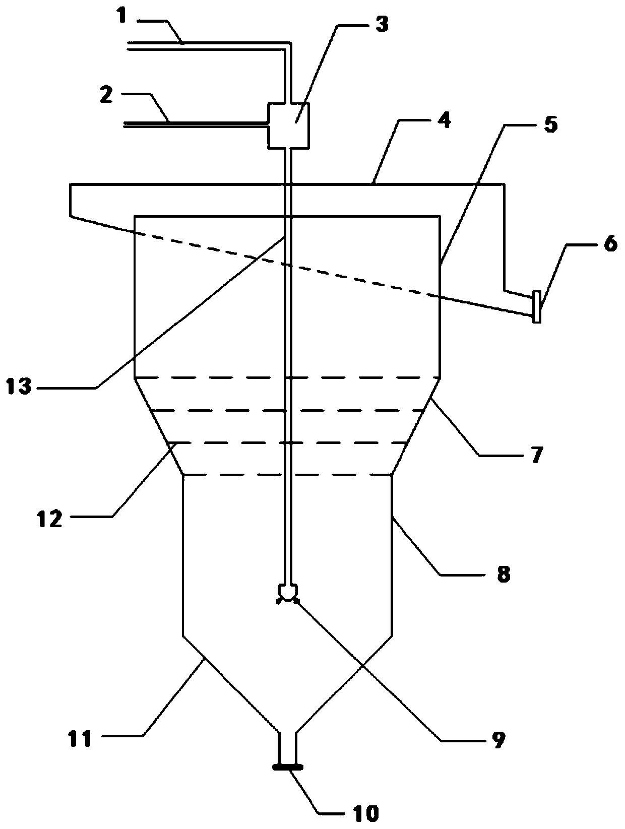
[0037] see figure 1 As shown, the flotation column device of the present invention includes a different-diameter flotation column and a jet mineralization system for supplying pulp to the different-diameter flotation column. The different-diameter flotation column includes an upper cylinder section 5 and a diameter smaller than the upper The lower cylindrical section 8 of the cylindrical section 5, the upper cylindrical section 5 and the lower cylindrical section 8 are connected by a tapered transition section 7, and the lower cylindrical section 8 is connected with the bottom con...


PUM


Abstract

The invention relates to mineral separation equipment, and discloses a flotation column device. The flotation column device comprises a different-diameter flotation column and a jet flow mineralization system used for supplying mineral pulp to the different-diameter flotation column; the different-diameter flotation column comprises an upper cylindrical section and a lower cylindrical section withthe diameter being smaller than that of the upper cylindrical section; the upper cylindrical section and the lower cylindrical section are connected through a conical transition section, and the lower cylindrical section is connected with a bottom conical section; a bubble collecting tank is arranged on the outer side of the upper end of the upper cylindrical section and connected with a bubble collecting pipe; and a tailing collecting pipe is arranged on the lower part of the bottom conical section. According to the flotation column device, colliding and adhesion of particles and bubbles areachieved in an appropriate turbulent environment; in a relatively-static fluid environment and under the large column body diameter, deadhesion of the coarse particles is reduced advantageously, meanwhile separation of useful minerals from gangue minerals is improved, and thus the separation efficiency is effectively improved; and the flotation column device has the advantages of being small in floor space, low in energy consumption and good in separation effect.

Description

technical field [0001] The invention belongs to mineral separation equipment, in particular to a flotation column device. Background technique [0002] The flotation column is an inflatable flotation machine that passes compressed air through a porous medium (aerator) to inflate and stir the pulp. There are microbubble countercurrent flotation columns and microbubble jet flotation columns. [0003] The flotation column is an important equipment for mineral flotation separation. It has the advantages of no mechanical stirring device, simple structure, small footprint, and low energy consumption. However, the main disadvantage of the flotation column is that the column is too high. Since the jet flotation column separates the mineralization system and the separation system independently, the height of the flotation column body is greatly reduced. The ore feeding point of the jet flotation column is usually set in the lower half of the column body. The flow rate of the slurry ...

Claims


Application Information

Patent Timeline
Patent Type & Authority Applications(China)
IPC IPC(8): B03D1/24
CPCB03D1/242
Inventor 王毓华卢东方郑霞裕李思李旭东薛子兴
Owner CENT SOUTH UNIV
Why Eureka
Try Eureka