Supercharge Your Innovation With Domain-Expert AI Agents!

A Method for Removing Carbon Deposition in Compressor Airway

A technology for compressors and carbon deposition, applied in cleaning methods and utensils, cleaning methods using liquids, chemical instruments and methods, etc., can solve problems such as long replacement cycles, heavy work, and unrealizable cleaning, so as to reduce operating intensity, Ease of operation and improvement of cleaning efficiency

Active Publication Date: 2022-06-03
ENRIC BENGBU COMPRESSOR
View PDF6 Cites 0 Cited by
  • Summary
  • Abstract
  • Description
  • Claims
  • Application Information

AI Technical Summary

Problems solved by technology

[0003] There are two commonly used methods to eliminate carbon deposits: first, replace parts, and replace all the parts that have formed carbon deposits. This method is feasible, but the cost is high. When the parts are out of stock, they need to be reprocessed, and the replacement cycle is longer. ;Second, manual cleaning; disassemble each part and clean the interior manually. This method is characterized by difficulty in cleaning and heavy work, and it cannot be cleaned thoroughly; when the inner cavity structure is more complicated, cleaning tools Unreachable, cleaning cannot be achieved, forming a dead angle
[0004] Patent Notification No. CN104190672A "Method for Removing Carbon Deposits in Gas Preheating Pipes" mentions a method that can remove carbon deposits in preheater tubes more quickly, and will not cause local overheating in places where there are more carbon deposits. The risk of local burnout method, but the reaction temperature is relatively high, it should be controlled at 500-1000°C, and the gas is easy to leak; Under operating conditions, a pulse signal is sent out in a timely manner, which can remove the original carbon deposits of the engine and prevent the formation of new carbon deposits, but this method requires a special device to emit pulse signals

Method used


Image

  • A Method for Removing Carbon Deposition in Compressor Airway
  • A Method for Removing Carbon Deposition in Compressor Airway
  • A Method for Removing Carbon Deposition in Compressor Airway

Examples


Embodiment 1

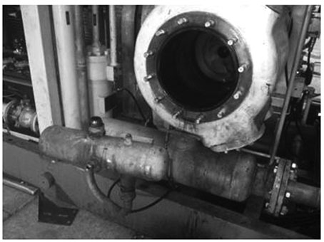
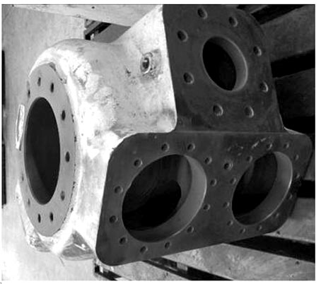
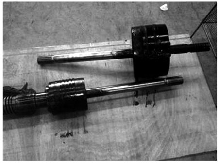
[0016] Example 1: Carbon deposit cleaning steps for our company's D121 products (pipes, coolers, separators, buffer tanks, cylinders, pistons, etc.):

[0017] A method for removing carbon deposits in an air passage of a compressor, the specific implementation steps are as follows:

[0018] (1) Take 3kg of sodium hydroxide (NaOH) and add it to 100L of water, stir and mix to make a NaOH solution;

[0019] (2) Put the cylinder in the heating tank (steel iron tank with a length of 2500mm, a width of 750mm, and a height of 700mm), so that the cylinder is completely submerged in the solution and is 30mm below the liquid level, and heated to boiling, and then continue to heat for 1 hour;

[0020] (3) Cover the heating tank and keep it warm for 8 hours so that the cylinder is immersed in the boiling liquid, then take out the cylinder and rinse it with clean water 3 times to remove all the carbon deposits, and use compressed air to blow off the water marks on the surface of the cylinde...


PUM


Abstract

The invention relates to a method for removing carbon deposits in the air duct of a compressor, which is characterized in that it comprises the following steps: (1) Sodium hydroxide and water are prepared into a solution at a volume ratio of 2-5:100; (2) The workpiece is placed in a heating tank Make the workpiece fully submerged and 20-50mm below the liquid surface, heat until boiling and continue heating for 1-2 hours; (3) Cover and keep warm for 8-12 hours, take out the workpiece, rinse with clean water 3-5 times, the surface of the workpiece Use compressed air to blow off traces, and coat the processed surface with gas-phase anti-rust oil for protection and anti-rust. The beneficial effect of the present invention is that the operation is simple, convenient, economical and practical; it not only reduces the work intensity of workers cleaning but also improves the cleaning work efficiency; the removal rate of carbon deposits reaches 100%, and there is no need to replace parts, and the parts can be cleaned and applied repeatedly; this method It can also be used to clean up carbon deposits in internal combustion engines, automobiles and other pipelines.

Description

technical field [0001] The invention belongs to the field of machinery manufacturing, relates to the technical field of compressors, and in particular relates to a method for removing carbon deposits in a compressor air passage. Background technique [0002] At the beginning of the design of compressor products (oil-lubricated compressors), the structural design of the hot zone of the exhaust system considers the time for oil particles to pass through the hot zone. It can ensure that the oil particles will not be oxidized in the hot zone and will not produce carbon deposits. However, when the lubricating oil is overfilled, the oil particles become larger particles, and the larger oil particles have larger mass and inertia. When the oil particles pass through the hot zone, the large oil particles cannot be carried away by the airflow, so they deposit. On the walls of the hot zone, it has been in contact with the air long enough for an oxidation reaction to occur and decompos...

Claims


Application Information

Patent Timeline
Patent Type & Authority Patents(China)
IPC IPC(8): B08B3/10B08B3/08B08B3/02F26B21/00
CPCB08B3/106B08B3/08B08B3/02F26B21/004B08B2203/007
Inventor 庞新勇杨威锋许跃俊
Owner ENRIC BENGBU COMPRESSOR
Features
  • R&D
  • Intellectual Property
  • Life Sciences
  • Materials
  • Tech Scout
  • Unparalleled Data Quality
  • Higher Quality Content
  • 60% Fewer Hallucinations
Learn More