High-speed air bearing motorized spindle

A technology of electric spindle and air flotation, which is applied in the direction of large fixed members, metal processing machinery parts, maintenance and safety accessories, etc., can solve the problems of lower processing accuracy, disadvantages of bearing capacity and support stiffness, wear of disc springs, etc., and achieve improvement Machining and assembly precision, eliminating the need for clamping and tool changing mechanisms, and improving the effect of heat dissipation

Pending Publication Date: 2019-10-25
HEFEI INSTITUTES OF PHYSICAL SCIENCE - CHINESE ACAD OF SCI
View PDF0 Cites 7 Cited by
  • Summary
  • Abstract
  • Description
  • Claims
  • Application Information

AI Technical Summary

Problems solved by technology

However, air bearings have disadvantages in terms of load capacity and support stiffness, and the problem of viscous shear friction and heat generation of air flow at high speeds is serious, resulting in reduced machining accuracy
At present, on the one hand, the built-in motors of the existing high-speed air-floating electric spindles mostly use high-speed AC asynchronous motors, and the motor squirrel cage rotors are directly processed by copper plating on the mandrel. This process is complicated and blocked by foreign technology, and has long relied on foreign countries In addition, the heat generated by the squirrel cage rotor of the AC asynchronous motor is not easy to dissipate, which directly leads to the corresponding thermal deformation of the mandrel
thereby reducing the machining accuracy
On the other hand, the existing high-speed air-floating electric spindle has a complex structure, including a complicated tool change mechanism. Long-term work is likely to cause wear or even failure of the internal disc spring. The bushing is composed of multiple parts, and the assembly process is complicated. After the electric spindle is assembled, it is difficult to ensure the coaxiality of the radial bearing and the perpendicularity between the thrust bearing and the rotation axis, which limits the further improvement of the machining accuracy of the electric spindle.

Method used


Image

  • High-speed air bearing motorized spindle
  • High-speed air bearing motorized spindle
  • High-speed air bearing motorized spindle

Examples


Embodiment Construction

[0070] The embodiments of the present invention are described in detail below. This embodiment is implemented on the premise of the technical solution of the present invention, and detailed implementation methods and specific operating procedures are provided, but the protection scope of the present invention is not limited to the following implementation example.

[0071] The embodiments of the present invention are described in detail below. This embodiment is implemented on the premise of the technical solution of the present invention, and detailed implementation methods and specific operating procedures are provided, but the protection scope of the present invention is not limited to the following implementation example.

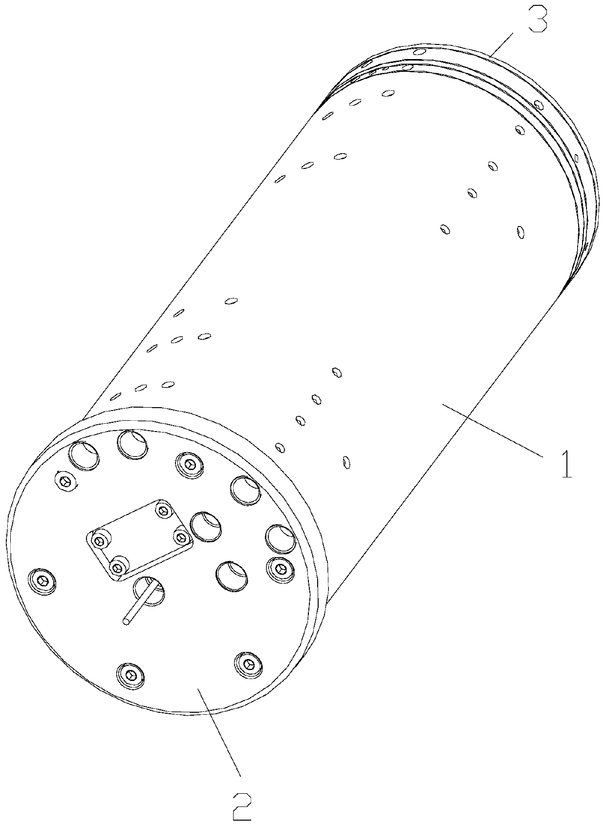
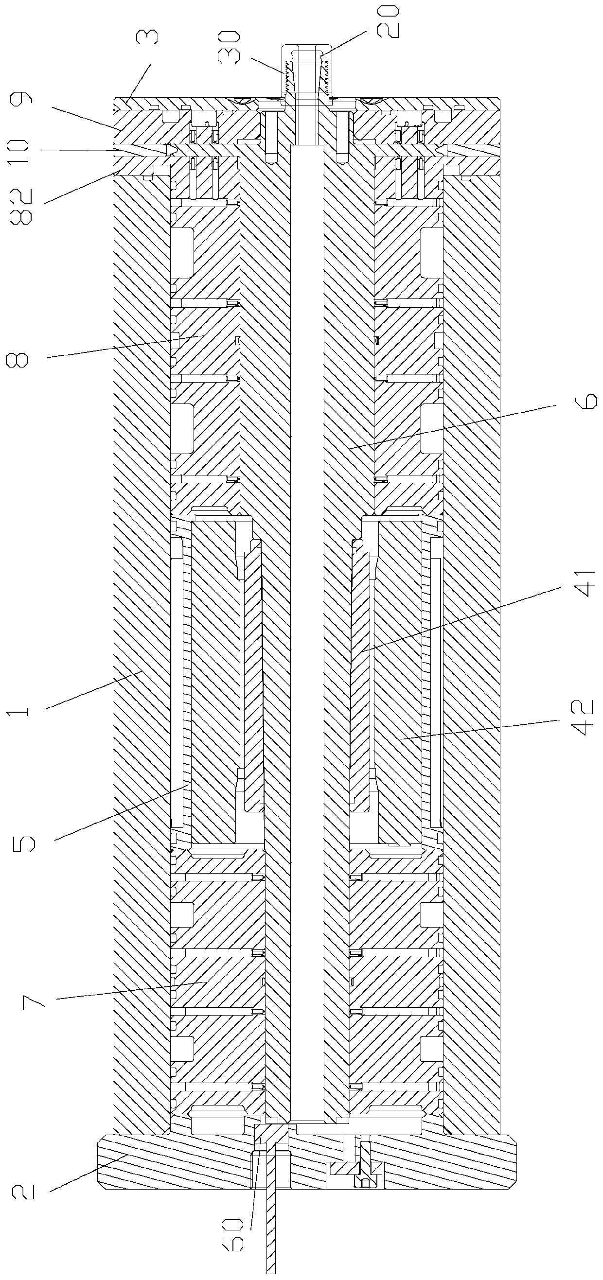
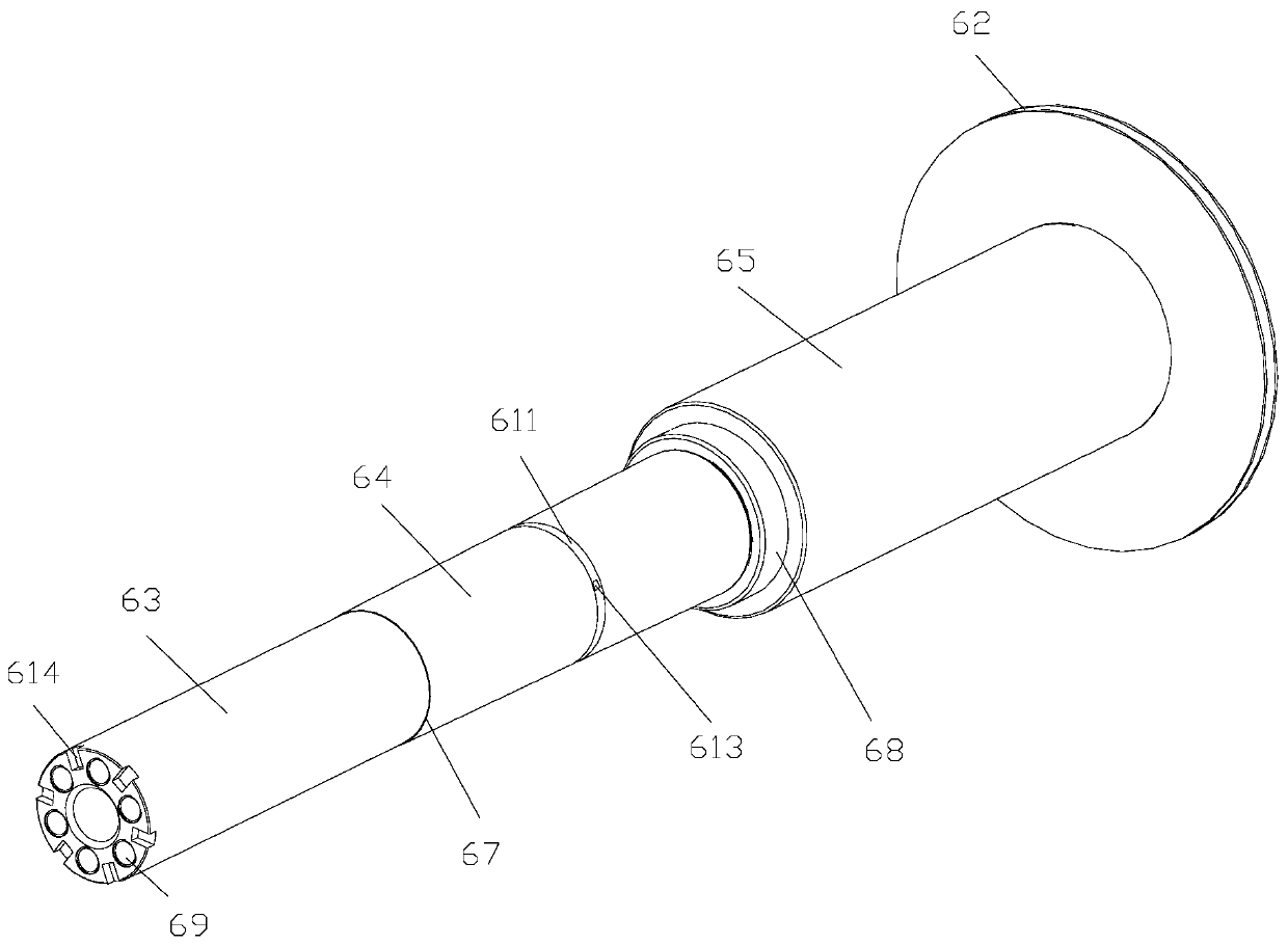
[0072] see Figure 1 to Figure 25 , This embodiment discloses a high-speed air-floating electric spindle, which includes a body assembly, a rotary assembly, a motor assembly 4, and an air-floating support assembly.

[0073]The body assembly includes a...


PUM


Abstract

The invention discloses a high-speed air bearing motorized spindle. The high-speed air bearing motorized spindle comprises a machine body assembly, a rotation assembly, a motor assembly and an air bearing support assembly. The rotation assembly comprises a mandrel arranged in a cavity of an outer casing. The air bearing support assembly comprises a left radial bearing, a radial thrust bearing, a right thrust bearing and a pneumatic structure. The left radial bearing, the motor assembly, the radial thrust bearing and the right thrust bearing are arranged side by side in the cavity of the outercasing from left to right. The position, close to the right end, of the mandrel is provided with a thrust disc. The radial thrust bearing and the right thrust bearing are arranged on the left side andthe right side of the thrust disc. A gap adjusting ring is arranged on the outer periphery of the thrust disc in a sleeving mode. High-pressure gas is introduced into gaps between the mandrel and bearings through a gas path structure, thus, a gas film is formed in the gaps between the mandrel and all the bearings, and the mandrel is suspended. The high-speed air bearing motorized spindle has theadvantages of high load bearing, rigidity, precision and heat dissipation capability and simple machining and assembly process.

Description

technical field [0001] The invention relates to the technical field of machining equipment, in particular to a high-speed air-floating electric spindle. Background technique [0002] The high-speed air-floating electric spindle is one of the core components of precision / ultra-precision machining equipment, which directly affects the final machining accuracy of the machining equipment. In the high-speed air-floating electric spindle, the motor rotor and the rotary mandrel are combined into one, supported by air bearings, and directly driven by the motor as a typical structural feature. It has the advantages of high rotation accuracy, high speed, and long life. However, air bearings have disadvantages in terms of load capacity and support stiffness, and the viscous shear friction and heat generation of air flow at high speeds are serious, resulting in reduced machining accuracy. At present, on the one hand, the built-in motors of the existing high-speed air-floating electric ...

Claims


Application Information

Patent Timeline
Patent Type & Authority Applications(China)
IPC IPC(8): B23B19/02B23Q1/70B23Q11/12
CPCB23Q1/70B23Q11/127
Inventor 高思煜施云高杨爽陈红徐林森朱佰新夏明张孝俣
Owner HEFEI INSTITUTES OF PHYSICAL SCIENCE - CHINESE ACAD OF SCI
Why Eureka
Try Eureka