
Semiconductor wafer electroplating clamping device

A clamping device and semiconductor technology, which is applied in the direction of semiconductor devices, circuits, electrolysis process, etc., can solve the problems of inability to ensure sufficient stirring of the electrolytic solution, poor clamping effect, poor electroplating effect, etc., to achieve rapid collection work and improve Effect, the effect of improving the clamping effect

Inactive Publication Date: 2019-10-25
扬州国润半导体科技有限公司
View PDF4 Cites 5 Cited by
  • Summary
  • Abstract
  • Description
  • Claims
  • Application Information

AI Technical Summary

Problems solved by technology

[0003] In the electroplating process of semiconductor wafers, electroplating fixtures are used to clamp and fix the wafers. However, the existing clamping devices have poor clamping effects and are prone to excessive force during the clamping process, resulting in damage to the wafers. The wear of the wafer, and the wafer is in the clamping process, the existing clamping device, when it is clamped and placed, the wafer is electroplated, and it is also easily blocked by the wafer clamp, resulting in poor electroplating effect. And it is impossible to ensure that the electroplating solution is fully stirred during electroplating

Method used


Image

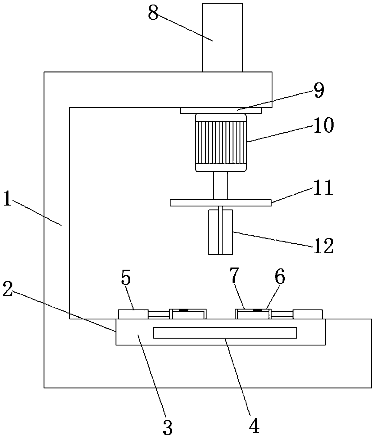
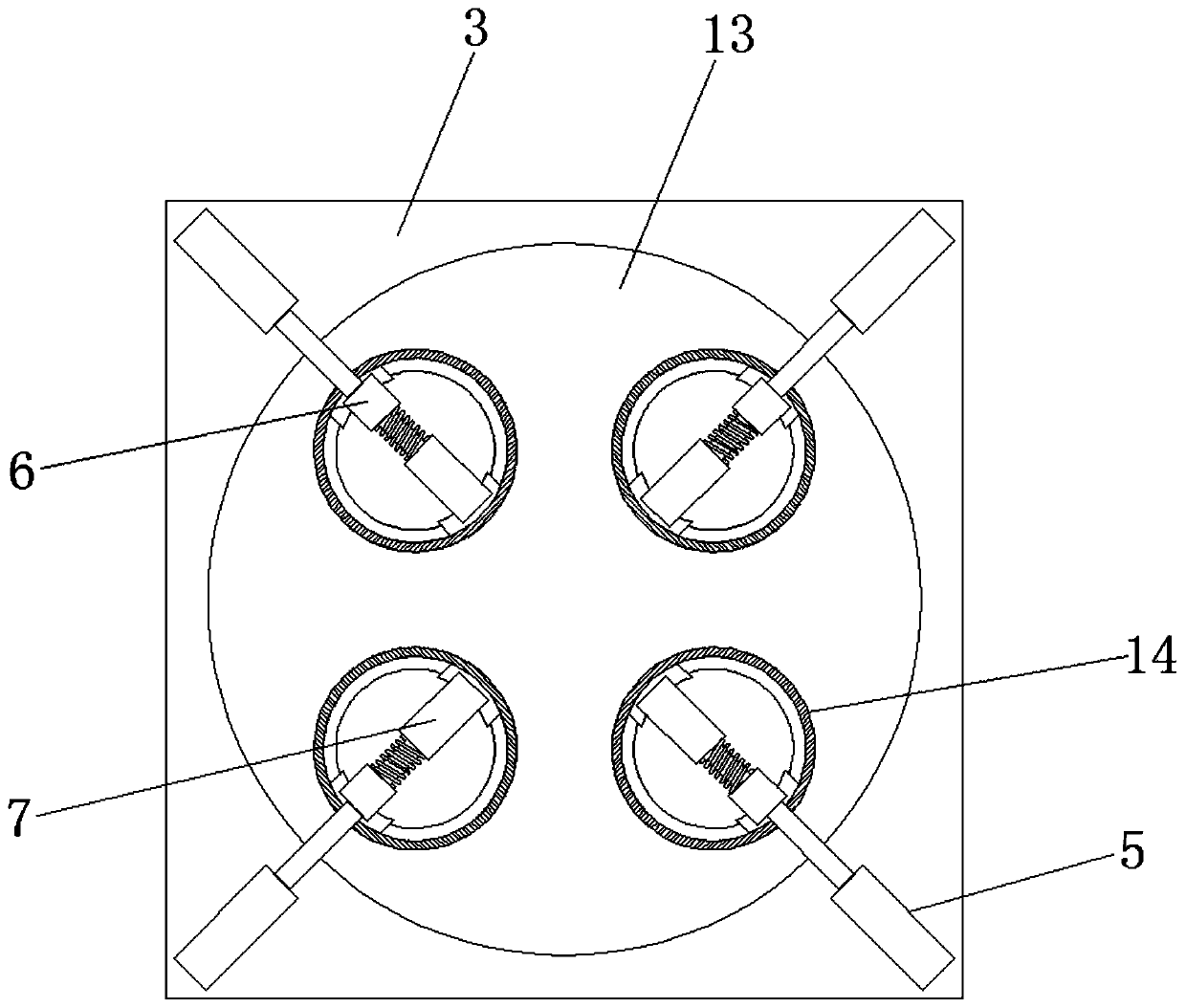
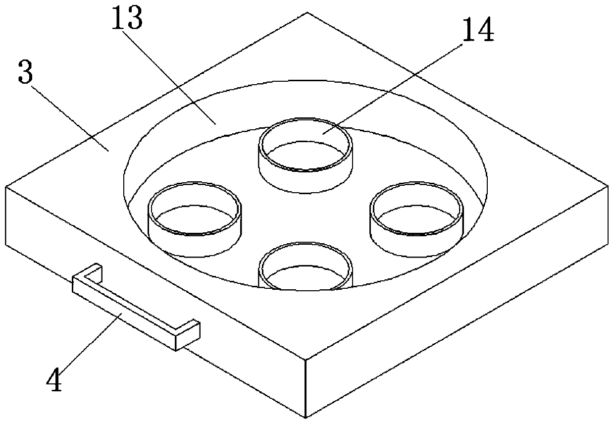
  • Semiconductor wafer electroplating clamping device
  • Semiconductor wafer electroplating clamping device
  • Semiconductor wafer electroplating clamping device

Examples


Embodiment Construction

[0019] The following will clearly and completely describe the technical solutions in the embodiments of the present invention with reference to the accompanying drawings in the embodiments of the present invention. Obviously, the described embodiments are only some, not all, embodiments of the present invention. Based on the embodiments of the present invention, all other embodiments obtained by persons of ordinary skill in the art without making creative efforts belong to the protection scope of the present invention.

[0020] The present invention provides such Figure 1-4 A semiconductor wafer electroplating clamping device shown includes a workbench 1, a hydraulic rod 8, a cylinder 5, a clamping main board 3 and an electroplating disc 14. The workbench 1 is an L-shaped structure, and its inner bottom end surface is provided with The bottom groove 2 which runs through horizontally and has a rectangular structure has a hydraulic rod 8 installed on its outer top surface away ...


PUM


Abstract

The invention discloses a semiconductor wafer electroplating clamping device. The device comprises a worktable, a hydraulic rod, a cylinder, a clamping main plate and an electroplating disc; the worktable is of an L-shaped structure, a transverse through bottom groove with a rectangular structure is formed in the bottom end surface of the inner side, a hydraulic rod is mounted on the side, far from the vertical end, of the top end surface of the outer side, and a support top plate is arranged on the top end surface of the inner side; the bottom end of a piston rod of the hydraulic rod penetrates through the worktable, and is fixedly welded with the support top plate; a motor vertically arranged is welded at the bottom end of the support top plate; and a machine shaft of the motor is connected with stirring blades through a support base plate. The semiconductor wafer electroplating clamping device can stir electroplating liquid in an electroplating tank, can guarantee full stirring andflowing of the electroplating liquid to guarantee the electroplating deposition thickness uniformity and to improve the electroplating effect, and finishes the clamping through cylinder pushing to achieve a better and more stable clamping effect.

Description

technical field [0001] The invention belongs to the technical field of semiconductor wafer electroplating, and in particular relates to a semiconductor wafer electroplating clamping device. Background technique [0002] In the production process of semiconductor integrated circuits, it is necessary to electroplate the surface of the wafer to form a metal layer. Therefore, wafer electroplating is one of the key links in the semiconductor wafer manufacturing process. The process is to place the wafer in the electroplating solution, connect the negative voltage to the wafer as the cathode, and connect the positive voltage to the soluble or insoluble anode. , the metal ions in the electroplating solution are deposited on the surface of the wafer through the action of an electric field. . [0003] In the electroplating process of semiconductor wafers, electroplating fixtures are used to clamp and fix the wafers. However, the existing clamping devices have poor clamping effects ...

Claims


Application Information

Patent Timeline
IPC IPC(8): C25D17/06C25D7/12
CPCC25D7/12C25D17/001C25D17/06
Inventor 徐宏进
Owner 扬州国润半导体科技有限公司
Learn More