Binocular-vision-positioning-technology-based method for measuring dynamic axis position of revolution body

A binocular vision positioning and measurement method technology, which is applied in the direction of measuring devices, optical devices, instruments, etc., can solve the problems affecting the measurement accuracy of the total station and the accuracy of laser ranging, and achieve fast measurement speed and high positioning accuracy , the effect of high measurement accuracy

Inactive Publication Date: 2019-10-25
朱承智
View PDF12 Cites 3 Cited by
  • Summary
  • Abstract
  • Description
  • Claims
  • Application Information

AI Technical Summary

Problems solved by technology

[0003] At present, the spatial position of the axis of the rotating body of the rotary kiln supporting wheel is mostly measured by a total station with a spherical prism. The ambient temperature of the rotary kiln is as high as 60°C when it is working, and the total station is a device for coordinate measurement by means of laser ranging. , the air turbulence at high temperature will affect the accuracy of the laser ranging and then affect the measurement accuracy of the total station; in addition, the total station needs to have a stable operating environment when measuring, and the rotary kiln may drive the foundation vibration when it is working, which will also affect the total station. Measuring accuracy of station instrument

Method used


Image

  • Binocular-vision-positioning-technology-based method for measuring dynamic axis position of revolution body
  • Binocular-vision-positioning-technology-based method for measuring dynamic axis position of revolution body
  • Binocular-vision-positioning-technology-based method for measuring dynamic axis position of revolution body

Examples


Embodiment Construction

[0030] The following examples are used to illustrate the present invention, but are not intended to limit the scope of the present invention.

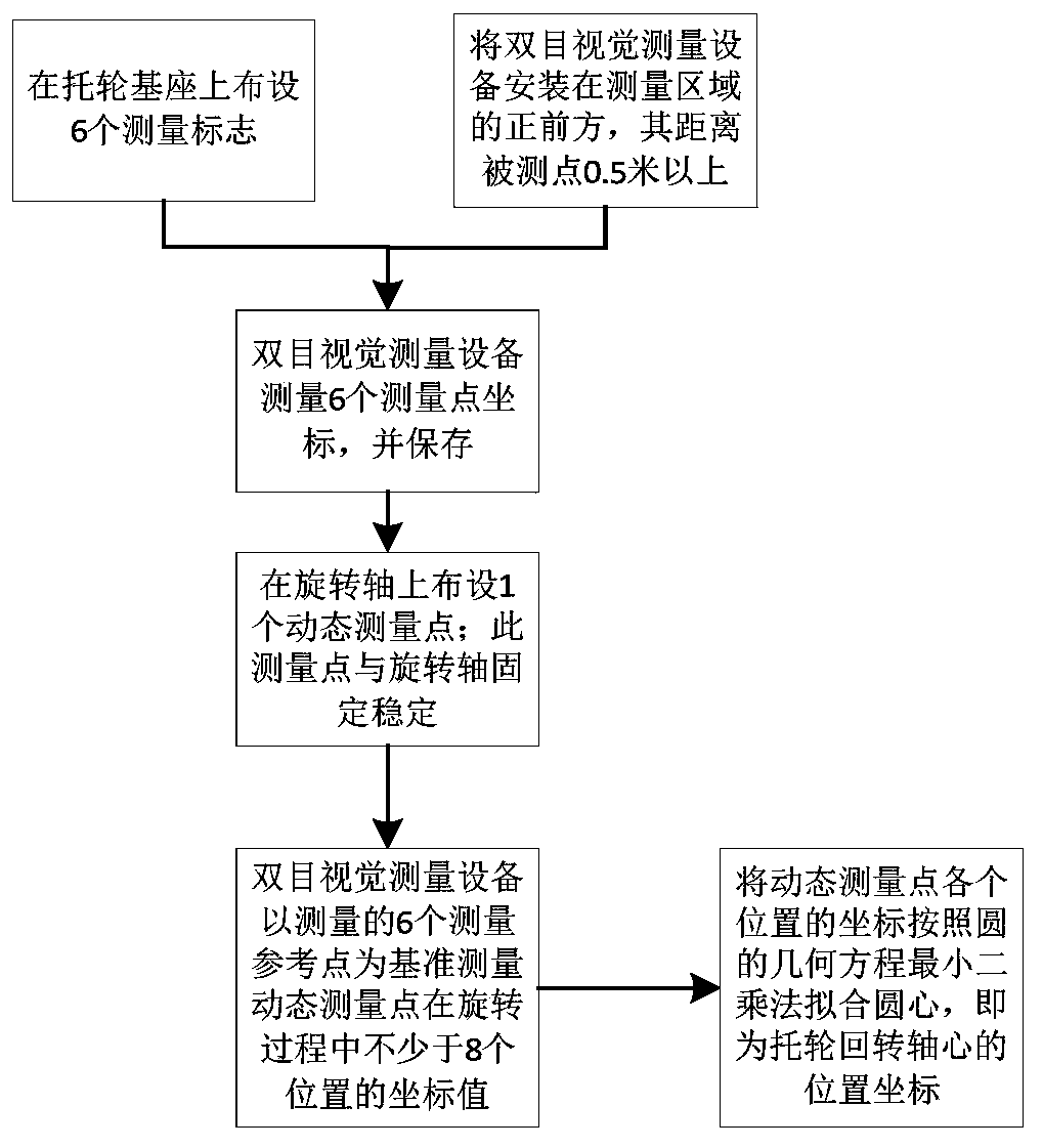
[0031] like figure 1 and Image 6 As shown, in this embodiment, the rotary body is selected as the supporting wheel of the rotary kiln, and the axis of the rotary body is located on the rotating shaft 1. The method for measuring the dynamic axis position of the rotary body based on the binocular vision positioning technology of the present invention includes the following steps:

[0032] step 1:

[0033] Arrange more than 6 measurement reference points A on the rotating shaft base 2, which are stable reference points for dynamic measurement, and need to be arranged at stable positions adjacent to the dynamic monitoring points. During the rotation of the rotating shaft 1, the measuring reference points A are relatively The rotating shaft base 2 should be stable.

[0034] Fix the binocular vision positioning device 3 in front of the m...


PUM


Abstract

The invention relates to an online measurement method for determining the spatial position of the axis of a revolution body, particularly to a binocular-vision-positioning-technology-based method formeasuring the dynamic axis position of a revolution body, thereby eliminating the influence on the measurement accuracy by the high temperature and vibration environment and improving the accuracy andreliability of measurement substantially. The method comprises: S01, arranging a plurality of measuring reference points on a support base of a revolution body and fixing a binocular vision positioning device in front of a measuring area; S02, measuring three-dimensional coordinates of the measuring reference points by using the binocular vision positioning device and setting the three-dimensional coordinates as measurement reference point coordinates; S03, arranging a dynamic measurement point stably at a rotation axis of the revolution body; S04, with the coordinate systems of the measuringreference points as references, measuring a coordinate value of the dynamic measurement point in the rotation process; and S05, carrying out circle center fitting on coordinates of multiple dynamic measuring points by referring to a circle standard equation based on a least squares method to obtain a spatial position of the revolution axis of the revolution body.

Description

technical field [0001] The invention relates to the technical field of spatial position measurement methods, in particular to a dynamic measurement method for the spatial position of the axis center of a revolving body based on binocular vision positioning technology. Background technique [0002] The rotary kiln is the core production equipment in the cement firing process. It is generally supported by three sets of supporting rollers. During the cement firing process, the supporting rollers support the rotary kiln to continue to rotate. In the long-term operation, due to the settlement of the rotary kiln base, the long-term thermal deformation of the support wheel and the wear during the rotation process, the axis of the rotary body of the support wheel will shift, which will cause the rotation resistance of the rotary kiln to increase and reduce the cement rotary kiln. The production efficiency of the system may even cause the rotary kiln to break down and reduce its work...

Claims


Application Information

Patent Timeline
Patent Type & Authority Applications(China)
IPC IPC(8): G01B11/27
CPCG01B11/27
Inventor 朱承智
Owner 朱承智
Why Eureka
Try Eureka