Test device and method for determining buoyancy of shield tunnel

A shield tunnel and model test device technology, which is applied in the field of test devices for determining the buoyancy during the excavation process of the shield tunnel, can solve the problem of making clear regulations on the anti-floating design and construction measures of the tunnel and failing to correctly reflect the construction period Tunnel anti-floating characteristics, tunnel anti-floating design and construction measures, etc., to achieve strong expansion, simple anti-sinking device, and avoid displacement

Active Publication Date: 2021-11-19
UNIV OF SHANGHAI FOR SCI & TECH
View PDF0 Cites 0 Cited by
  • Summary
  • Abstract
  • Description
  • Claims
  • Application Information

AI Technical Summary

Problems solved by technology

The traditional anti-floating design fails to consider the buoyancy dynamic factors of the tunnel in the time-varying grout, so it fails to correctly reflect the anti-floating characteristics of the tunnel during the construction period, and the current relevant design codes do not make clear the anti-floating design and construction measures of the tunnel. According to the regulations, with the increasing diameter of shield tunnels, the anti-floating problem will become the bottleneck for the development of soft soil shield tunnels to super-large diameters. The design specification does not make clear regulations on the anti-floating design and construction measures of the tunnel. With the continuous increase of the diameter of the shield tunnel, the anti-floating problem will become a bottleneck for the development of soft soil shield tunnels to super-large diameters.

Method used


Image

  • Test device and method for determining buoyancy of shield tunnel
  • Test device and method for determining buoyancy of shield tunnel
  • Test device and method for determining buoyancy of shield tunnel

Examples


Embodiment Construction

[0026] The present invention will be further described in detail through a preferred embodiment below in conjunction with the accompanying drawings.

[0027] First, make a model box, a segment lining model of a rectangular tunnel, and a set of total weight control devices for a rectangular tunnel.

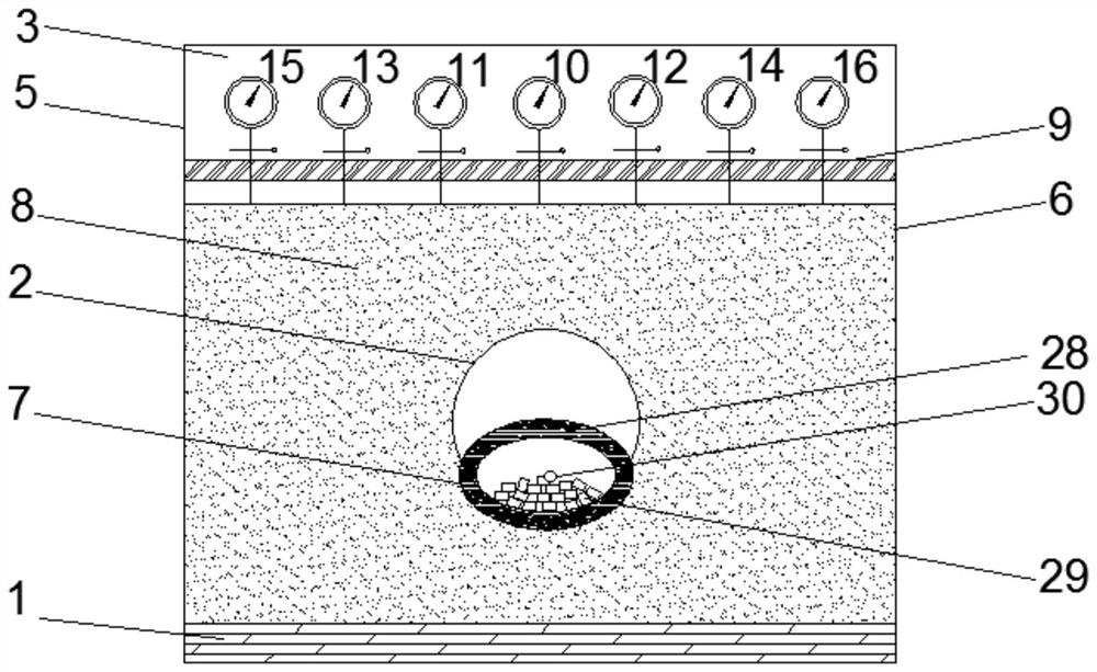
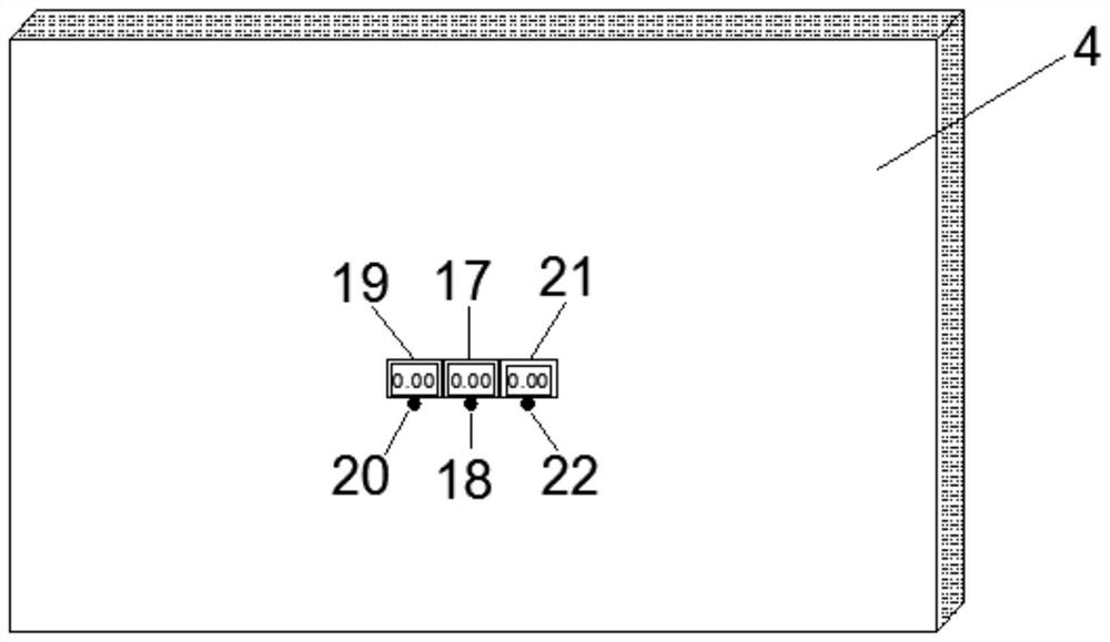
[0028] like figure 1 As shown, the shape of the model box is a cuboid, the internal space size is 2200mm×1500mm×1800mm (length×width×height), the bottom is made of a wooden board 1 of 2200mm×1500mm×30mm (length×width×thickness), and the front is 2200mm×1830mm ×20mm (length×height×thickness) toughened glass 3 with a radius of 150mm circular glass orifice 2, the center of the circular glass orifice is located in the center of the tempered glass 3, and the back is 2200mm×1830mm×20mm (length×height× thick) plank 4, the left side is a plank 5 of 1530mm×1830mm×20mm (width×height×thickness), the right side is a plank 6 of 1500mm×1830mm×20mm (length×height×thickness), the bottom and plank...


PUM

PropertyMeasurementUnit
radiusaaaaaaaaaa

Abstract

The invention relates to a model test device and method for determining the buoyancy of a shield tunnel. The model box is filled with collapsible loess of different weights to simulate different working conditions, and a similar rectangular tunnel tube is placed horizontally at the circular glass opening of the simulation box. The sheet lining model includes double PVC pipes, and fresh slurry is filled between the double pipe rings. The segment lining model of a rectangular tunnel is equipped with a total weight control device for a rectangular tunnel. The control device includes PVC pipes and resistance wires pasted on the inside of the pipes. , 5kg of columnar dry ice placed inside the tube, exhaust hose, valve, anhydrous alcohol tank, etc., three laser displacement meters are pasted on the back plate of the model box, and the emission of carbon dioxide is controlled by observing whether the position of the projection point changes. Find the critical state of slurry floating in the model tunnel at different ages in time; change the collapsible loess surface in the simulation box and fix the seven displacement gauges through the displacement gauge brackets, and record the seven displacement counts to simulate the freedom during the shield tunnel excavation process. deformation of the soil surface.

Description

technical field [0001] The invention relates to a test device for determining the buoyancy force during the excavation process of a shield tunnel, in particular to a model test device for the influence of the grout buoyancy on the deformation of the tunnel itself and free soil during the excavation process of the shield tunnel. Background technique [0002] With the extensive development of underground tunnel engineering construction, more and more complex working conditions and construction problems have emerged one after another. At present, the influence of buoyancy in the excavation process of shield tunnels is generally through 1. Only relying on its own weight and covering soil can meet the anti-floating requirements through calculation. 2. Because there is no roof and soil cover in the light transition section and open section of the tunnel, generally speaking, it cannot meet the anti-floating requirements by its own weight, and an inverted filter layer structure can ...

Claims


Application Information

Patent Timeline
Patent Type & Authority Patents(China)
IPC IPC(8): G01N33/24E21D9/06
CPCE21D9/06G01N33/24
Inventor 张治国沈安鑫程志翔王志伟
Owner UNIV OF SHANGHAI FOR SCI & TECH
Why Eureka
Try Eureka