Low SNR signal parameter extraction method based on pulse cutting

A pulse signal and low signal-to-noise ratio technology, applied in the radar field, can solve problems affecting the accuracy of parameter extraction, pulse signal submersion, and unsuitable signal grouping calculations, etc., to achieve high precision and improve the effect of signal-to-noise ratio

Active Publication Date: 2019-10-25
XIDIAN UNIV
View PDF5 Cites 9 Cited by
  • Summary
  • Abstract
  • Description
  • Claims
  • Application Information

AI Technical Summary

Problems solved by technology

In general, when the pulse signal level and the noise level are clearly separable, a fixed noise threshold can be set to detect the signal. The level-limited part is the noise part of the signal, and the pulse repetition time PRT of the detected pulse signal is used to accurately group the signal, but under the condition of low signal-to-noise ratio, the acquired pulse signal itself is submerged in the noise In the signal, it is difficult to use the traditional algorithm of threshold detection to distinguish the signal from the noise, and it becomes very difficult to accurately group the pulse signal, which will inevitably affect the accuracy of subsequent parameter extraction
[0006] Chinese patent CN 106877901A proposes a method for detecting signals under low signal-to-noise ratio conditions by detecting signal power spectrum and performing band-pass filtering; Chinese patent CN 105072067B proposes to use the cep

Method used


Image

  • Low SNR signal parameter extraction method based on pulse cutting
  • Low SNR signal parameter extraction method based on pulse cutting
  • Low SNR signal parameter extraction method based on pulse cutting

Examples


Embodiment Construction

[0029] The technical solutions in the embodiments of the present invention will be clearly and completely described below in conjunction with the accompanying drawings. Apparently, the described embodiments are only some, not all, embodiments of the present invention. Based on the embodiments of the present invention, all other embodiments obtained by persons of ordinary skill in the art without making creative efforts belong to the protection scope of the present invention.

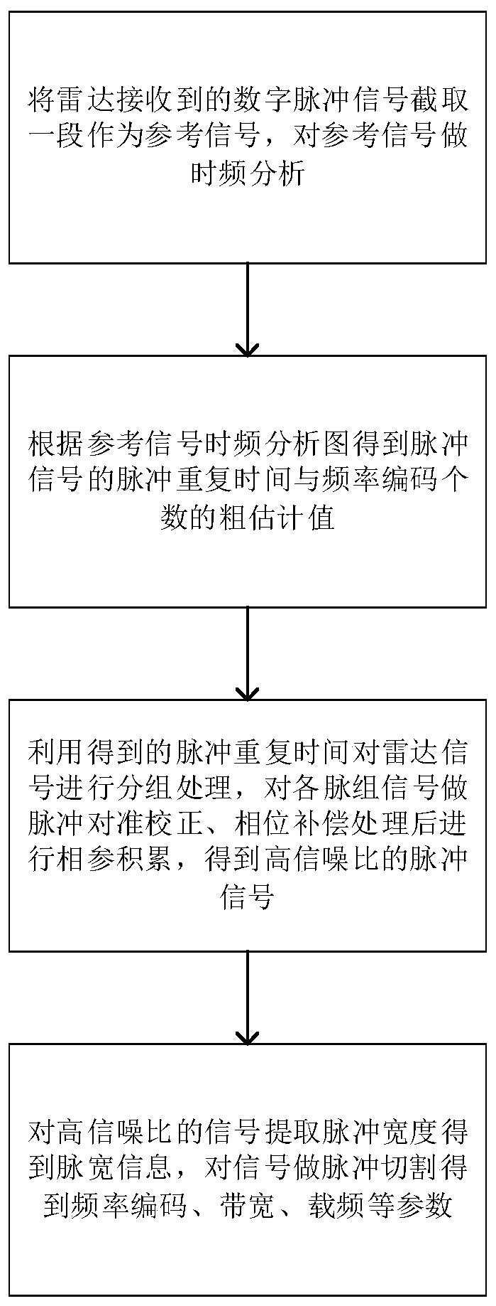
[0030] refer to figure 1 , a method for extracting parameters of a discrete frequency coded pulse signal based on pulse cutting in the case of a low signal-to-noise ratio provided by an embodiment of the present invention, comprising the following steps:

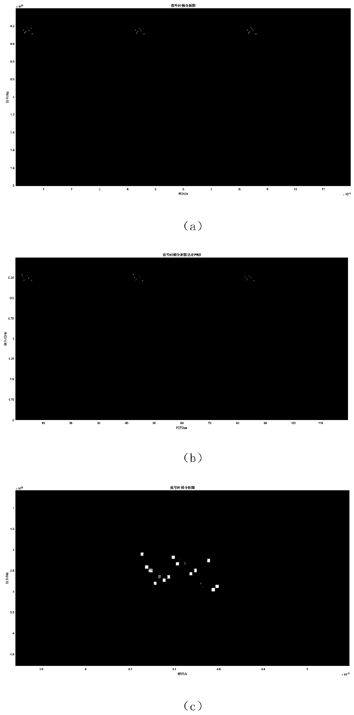
[0031] Step 1: Calculate the time-frequency diagram of the reference signal, and extract the pulse repetition time and the number of frequency codes.

[0032] The radar receives the radar pulse signal transmitted by the other party through the radar r...


PUM


Abstract

The invention discloses a low SNR (signal noise ratio) signal parameter extraction method based on pulse cutting, and a problem that parameters of a discrete frequency coded signal are difficult to extract under the condition of a low SNR in the prior art mainly is solved. The implementation scheme comprises a step of intercepting one section of digital pulse signals received by a radar to be a reference signal and performing short-time Fourier transform on the reference signal to obtain a time-frequency diagram, a step of obtaining a pulse repetition time estimation value of the radar pulse signal and the number of frequency codes by using the time-frequency diagram, and a step of grouping the digital pulse signals by the pulse repetition time, and sequentially performing pulsed alignmentcorrection, phase compensation and coherent accumulation on the grouped signals to obtain accumulated signals with a high SNR, and obtaining estimated results of pulse width, bandwidth, carrier frequency and frequency code of a radar pulse signal. According to the method, the parameters of a discrete frequency coded signal can be effectively extracted under the condition of the low SNR, the parameter precision is high, and the method can be used for processing and analyzing a discrete frequency code pulse signal.

Description

technical field [0001] The invention belongs to the technical field of radar, in particular to a signal parameter extraction method with low signal-to-noise ratio, which is suitable for processing and analyzing discrete frequency coded pulse signals. Background technique [0002] The ground base station radar receives the direct wave pulse signal emitted by the opponent's radar, and the signal passes through the radar receiver, and is converted into a baseband signal by down-conversion processing. The signal amplitude is amplified by an operational amplifier, and then converted into a digital pulse signal through AD conversion. The signal threshold is defined for pulse detection, and then a series of parameter extraction operations are performed on the detected pulse signal. [0003] However, in actual work, the signal received by the ground base station radar is generally the signal emitted by the beam sidelobe of the opponent's radar, and the pulse signal level obtained af...

Claims


Application Information

Patent Timeline
IPC IPC(8): G01S7/02G01S7/292G01S7/40
CPCG01S7/023G01S7/292G01S7/40
Inventor 张磊魏嵩张曼孙希平
Owner XIDIAN UNIV
Why Eureka
Try Eureka