
Synthetic Aperture Lidar System

A technology of synthetic aperture laser and radar systems, applied in the field of synthetic aperture laser radar systems, can solve the problems of compensation, inability to greatly improve the imaging resolution, limited effect of phase error, etc., and achieve the effect of high-resolution imaging

Active Publication Date: 2021-02-05
SPACETY CO LTD (CHANGSHA)
View PDF14 Cites 0 Cited by
  • Summary
  • Abstract
  • Description
  • Claims
  • Application Information

AI Technical Summary

Problems solved by technology

However, the improved system provided by this patent also does not monitor and compensate the nonlinearity of the tunable laser source in real time, and the optical bandwidth filter has a limited effect on the phase error caused by atmospheric turbulence and platform vibration in the azimuth direction, and cannot greatly Increased imaging resolution in azimuth

Method used


Image

  • Synthetic Aperture Lidar System

Examples


Embodiment 1

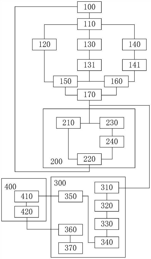
[0046]This embodiment discloses a synthetic aperture laser radar system, which at least includes a tunable laser module 100 arranged on a flight vehicle platform. The system also includes a feedback control module 200 , an imaging module 300 and a phase compensation module 400 . The chirp signal light generated by the tunable laser module 100 enters the target channel 120 , the common channel 130 and the reference channel 140 for outputting the detection signal light and receiving the echo beam respectively through the optical splitter 110 to generate a difference frequency signal. The feedback control module 200 generates a time-frequency signal of the frequency difference signal through the phase shifter 210 based on the frequency difference signal. The feedback control module 200 generates a phase difference value representing the linearity of the chirp signal light in real time based on the time-frequency signal. The feedback control module 200 drives the tunable laser mo...


PUM


Abstract

The present invention relates to a synthetic aperture laser radar system, including at least a tunable laser module arranged on a flight vehicle platform, the system also includes a feedback control module, an imaging module and a phase compensation module, and the chirp signal light generated by the tunable laser module is respectively Enter the target channel, common channel and reference channel to generate a difference frequency signal, and the feedback control module drives the tunable laser module to tune in real time based on the difference frequency signal so that the phase difference value remains constant to avoid distance distortion. In the imaging module based on the difference frequency signal imaging During the process, the phase compensation module gradually approaches the residual phase in the difference frequency signal in an iterative manner to compensate and avoid azimuth distortion. The invention can monitor and compensate the nonlinearity of the frequency-modulated laser source in real time, and can also compensate the non-ideal optical path caused by the atmospheric turbulence and the vibration of the satellite platform to realize high-resolution imaging in the range direction and the azimuth direction.

Description

technical field [0001] The invention relates to the technical field of radar, in particular to a synthetic aperture laser radar system. Background technique [0002] Lidar is a high-sensitivity radar with high resolution, good concealment, small size, light weight, strong anti-interference ability, and insensitive to multi-path effects. It can detect stealth aircraft, submarines, and biological and chemical warfare agents. However, the lidar beam is narrow, not suitable for large-scale search, and it is greatly affected by the atmosphere and weather, making it difficult to search and capture targets. Moreover, its spatial resolution is limited by the optical aperture and decreases with the increase of distance. Therefore, a new system of lidar—Synthetic Aperture Laser Radar (SAL) emerged as the times require. [0003] The working principle of SAL is similar to that of Synthetic Aperture Radar (SAR), except that the transmitted signal is different. It achieves high resolutio...

Claims


Application Information

Patent Timeline
Patent Type & Authority Patents(China)
IPC IPC(8): G01S17/90G01S7/497
CPCG01S7/497G01S17/90
Inventor 杨峰任维佳杜志贵陈险峰
Owner SPACETY CO LTD (CHANGSHA)
Learn More