Cell observation apparatus

A technology for observing devices and cells, which is used in biochemical cleaning devices, enzymology/microbiology devices, image data processing, etc., and can solve problems such as lack of reflection, difficulty in grasping where cells exist in a well, and omissions by observers. , to achieve the effect of improving efficiency

Inactive Publication Date: 2019-10-25
SHIMADZU SEISAKUSHO CO LTD
View PDF4 Cites 0 Cited by
  • Summary
  • Abstract
  • Description
  • Claims
  • Application Information

AI Technical Summary

Problems solved by technology

However, in the phase information obtained by computational processing such as backlight propagation calculations based on hologram data, only information about objects with a relatively small optical thickness, that is, a low phase difference, such as cells, is reflected, and almost no information is reflected. Information about objects such as containers that have an optical thickness greater than that of cells
This is because, in general holographic microscopes, it is difficult in principle to measure the optical depth only up to the wavelength of the light source used.
[0006] Therefore, for example, even if a phase image of the entire cell culture plate is displayed, it is almost impossible to visually recognize the shape of the storage portion (well) formed on the cell culture plate, so that it is difficult for the observer to grasp which well the observed cell exists in. questions like location
In addition, there is another problem that even if foreign matter such as human hair or dust that is larger than the cell is mixed into the cell culture container, the foreign matter cannot be clearly displayed on the phase image, causing the observer to overlook it.

Method used


Image

  • Cell observation apparatus
  • Cell observation apparatus
  • Cell observation apparatus

Examples


Embodiment Construction

[0044] Next, an embodiment of the cell observation device according to the present invention will be described with reference to the drawings.

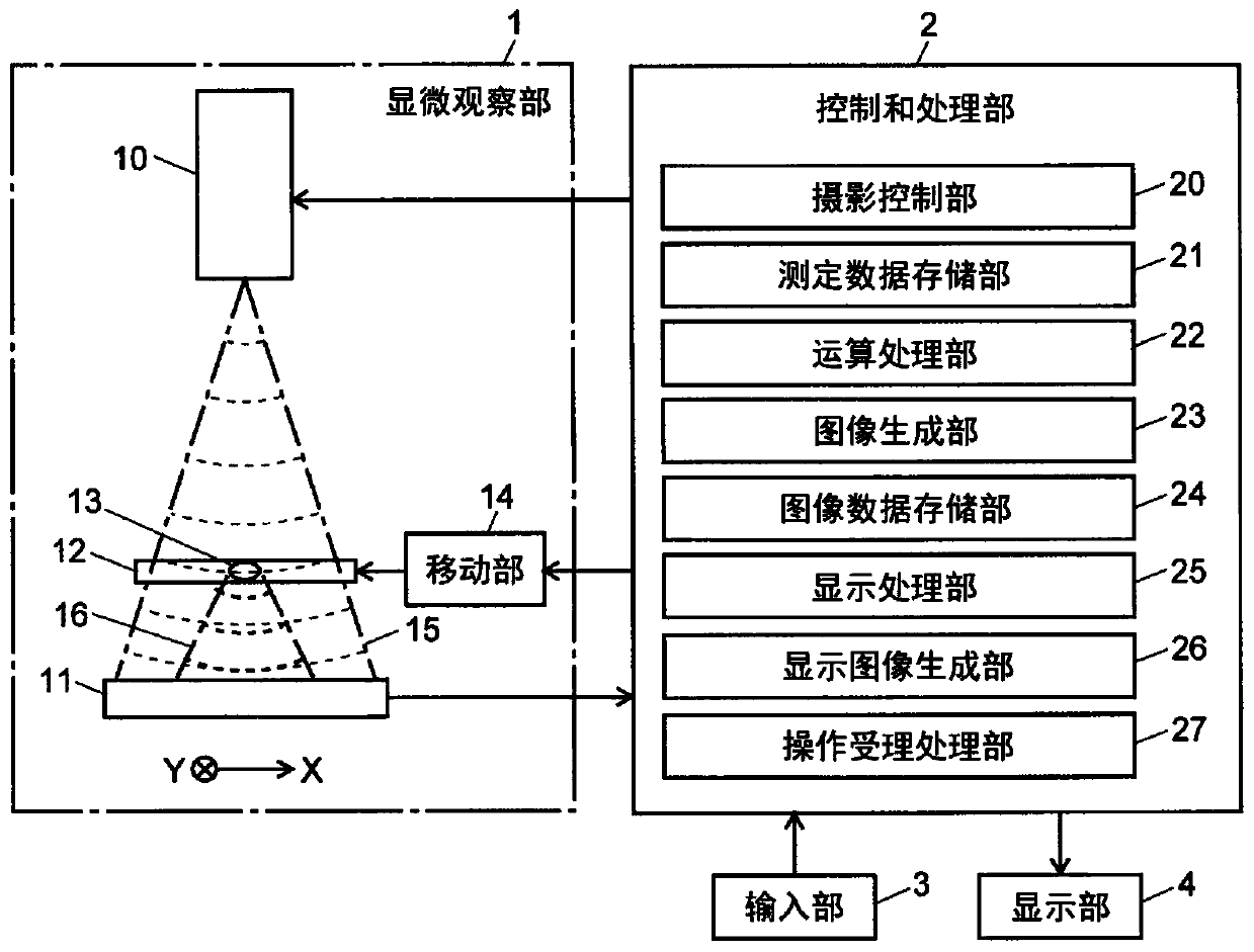
[0045] figure 1 It is a structural diagram of the main part of the cell observation device of this embodiment.

[0046] The cell observation device of this embodiment includes a microscopic observation unit 1 , a control and processing unit 2 , an input unit 3 as a user interface, and a display unit 4 .

[0047] The microscopic observation unit 1 is a coaxial holographic microscope (In-line Holographic Microscopy: IHM), equipped with an image sensor 11 and a light source unit 10 including a laser diode, etc. The cell culture plate 12 of the subject's cells 13 . The cell culture plate 12 is freely movable in two axial directions, X-axis and Y-axis, which are perpendicular to each other, by a moving unit 14 including a driving source such as a motor, for example.

[0048] The control and processing section 2 controls the operation o...


PUM

PropertyMeasurementUnit
sizeaaaaaaaaaa

Abstract

The present invention is a cell observation apparatus whereby a two-dimensional distribution of phase information and intensity information is calculated on the basis of hologram data obtained by a holographic microscope, an image display field (120) in which two image display frames (121, 122) are provided being disposed in an image display screen image (100) displayed in a display unit. In the image display frames (121, 122), a phase image and an intensity image, respectively, corresponding to the same observation range are displayed on a cell culture plate (12) in which cells as an observation object are cultured. In the intensity image, a well on the plate that is almost invisible in the phase image can clearly be identified. By contrast, in the phase image, living cells that are almost invisible in the intensity image can be observed. An observer therefore determines a range to be observed in a well in the intensity image, and magnifies the determined range and observes cells in detail in the phase image. Cells that are present in the range to be observed in a well can thereby be positively observed.

Description

technical field [0001] The present invention relates to a cell observation device for observing the state of cells, and more specifically, to a method for generating a hologram obtained by a digital holographic microscope and recording interference fringes of an object wave and a reference wave. A cell observation device for phase images, intensity images, etc. of objects. Background technique [0002] In recent years, research using pluripotent stem cells such as iPS cells and ES cells has become popular in the field of regenerative medicine. In general, cells are transparent and difficult to observe with a normal optical microscope, so cells have been widely observed using a phase-contrast microscope in the past. [0003] However, in the case of a phase contrast microscope, focusing is required when taking a microscopic image. Therefore, in the case of acquiring a microscopic image of each small area obtained by finely dividing a wide observation target area, there is a p...

Claims


Application Information

Patent Timeline
Patent Type & Authority Applications(China)
IPC IPC(8): G01N21/41C12M1/34G02B21/00G03H1/00
CPCC12M1/34G01N15/1434G01N15/1468G01N2015/1006G01N2015/1454G03H1/0443G03H1/0866G03H2001/0447G06T3/40G06T7/0012G06T2207/10056G06T2207/30024G01N21/41G02B21/00G03H1/0005G03H2001/005G03H2001/0452G03H2210/12G03H2210/55
Inventor 青位祐辅木村克利
Owner SHIMADZU SEISAKUSHO CO LTD
Why Eureka
Try Eureka