Eureka AIR delivers breakthrough ideas for toughest innovation challenges, trusted by R&D personnel around the world.

Multi-station assembly line type wire electrical discharge machining equipment for cracking groove of connecting rod

A pipeline type, cracking tank technology, applied in electric processing equipment, metal processing equipment, manufacturing tools, etc., can solve the problems of expensive imported laser heads, affecting the processing accuracy of equipment, and increasing the difficulty of workpiece clamping, reducing the risk of being easily damaged. Collision, increase the cost of the station, increase the effect of the station

Active Publication Date: 2019-10-29
GUANGDONG UNIV OF TECH
View PDF9 Cites 4 Cited by
  • Summary
  • Abstract
  • Description
  • Claims
  • Application Information

AI Technical Summary

Problems solved by technology

[0005] Although the existing laser grooving has the characteristics of dry cutting and high efficiency, the equipment cost is high, and the imported laser head is expensive, even exceeding 50% of the overall equipment cost
Moreover, laser cutting is prone to produce high-hardness slag, which will cause tool chipping in the subsequent fine boring process
[0006] The connecting rod cracking groove device mentioned in the patent CN101125379A, because the "U" structure is designed at the bottom of the workbench, when clamping the connecting rod, it is necessary to pass the big end hole of the connecting rod through the supporting rod from above the supporting rod. It is easy for the connecting rod to collide with the "U" structure when clamping the connecting rod, which not only increases the difficulty of clamping the workpiece, but also may cause the deformation of the "U" structure and affect the processing accuracy of the equipment
And the efficiency of wire cutting and grooving equipment for a single station is lower than that of laser grooving equipment

Method used


Image

  • Multi-station assembly line type wire electrical discharge machining equipment for cracking groove of connecting rod
  • Multi-station assembly line type wire electrical discharge machining equipment for cracking groove of connecting rod
  • Multi-station assembly line type wire electrical discharge machining equipment for cracking groove of connecting rod

Examples


Embodiment 1

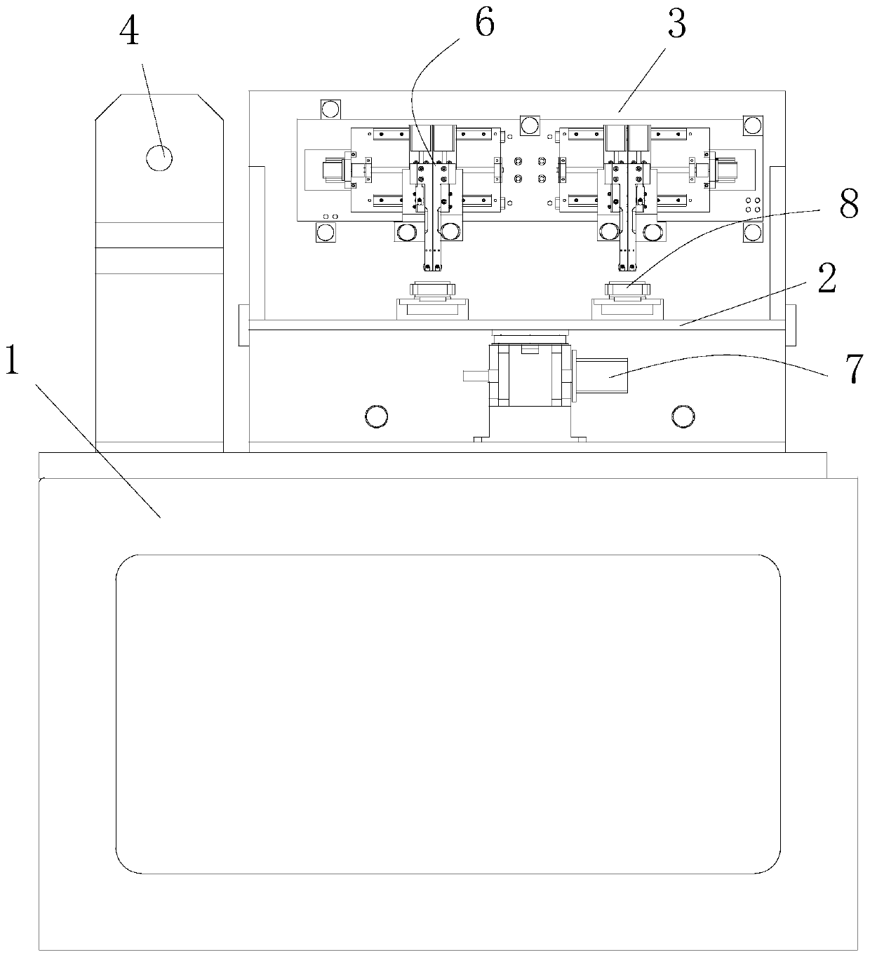
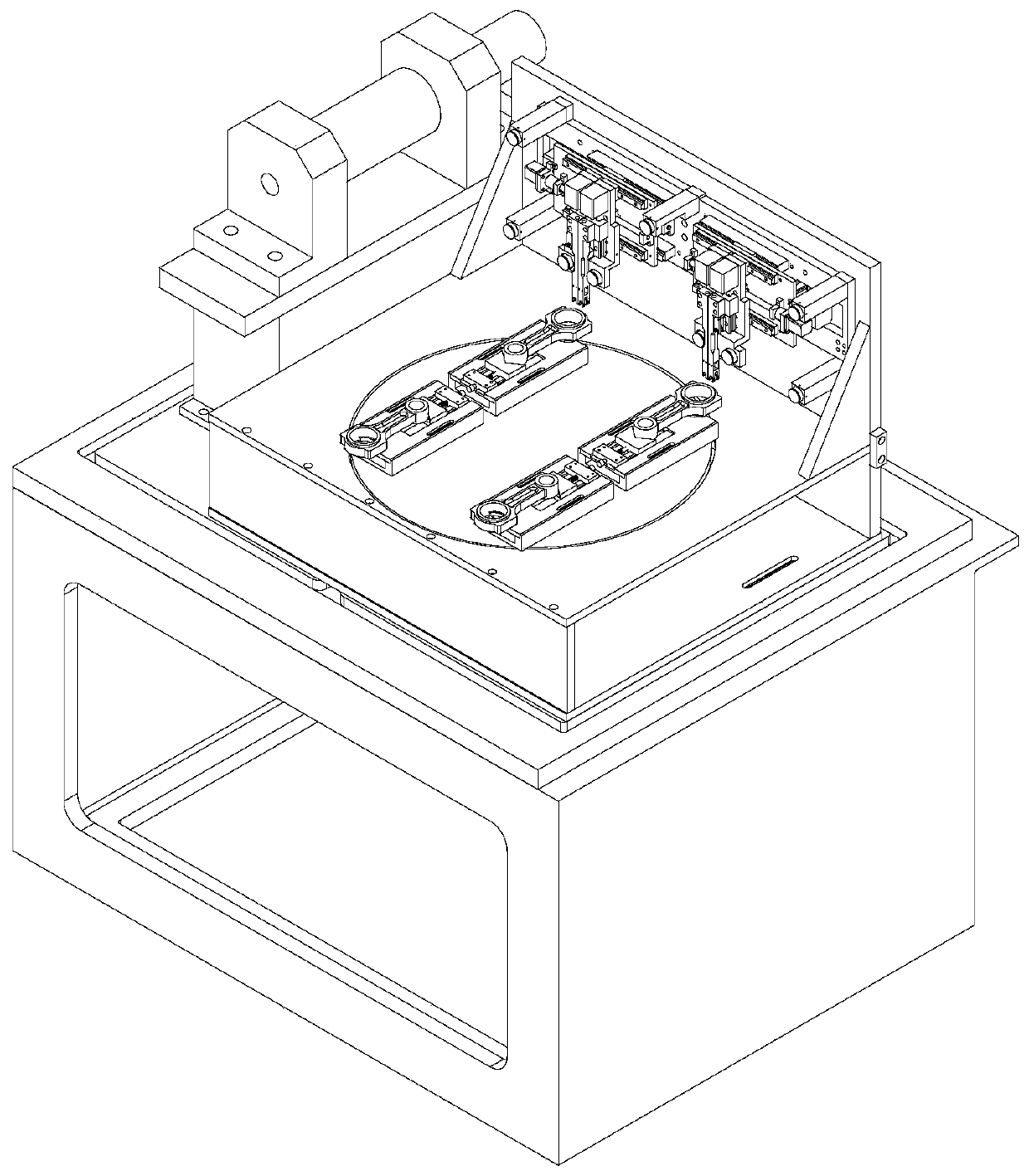
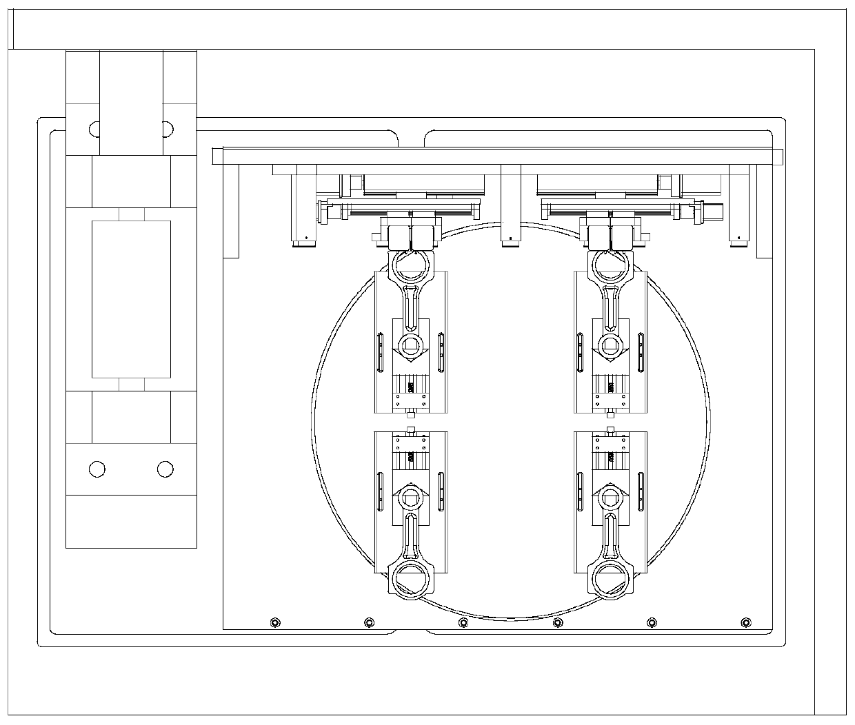
[0049] like Figure 1 to Figure 4 As shown, this embodiment discloses a multi-station assembly line connecting rod cracking groove line cutting equipment, the groove cutting equipment mainly includes a frame 1, a workbench 2, a back plate 3, a winding drum 4, an electrode wire 5, Grooving mechanism 6, rotating mechanism 7, and adjustable anti-collision clamp 8.

[0050] Specifically, the frame 1 is fixedly arranged. The workbench 2 is installed on the frame 1 and is fixedly connected with the frame 1 . The winding drum 4 is fixed on the frame 1 and is located on one side of the workbench 2 . The backboard 3 is vertically arranged on the workbench 2 and is fixedly connected with the workbench 2 . The grooving mechanism 6 is fixedly installed on the back plate 3 and connected to the winding drum 4 through the electrode wire 5 . The rotating mechanism 7 is arranged in the workbench 2, and its output end is fixedly connected with the adjustable anti-collision fixture 8, and dr...


PUM


Abstract

The invention discloses a multi-station assembly line type wire electrical discharge machining equipment for a cracking groove of a connecting rod. The grooving equipment mainly comprises a machine frame, a workbench, a back plate, a wire winding cylinder, an electrode wire, a grooving mechanism, a rotating mechanism and adjustable anti-collision clamps. According to the equipment, during use, a worker installs a connecting rod workpiece on a clamp panel at a feeding station and then releases a locking block, and the locking block abuts against the connecting rod under the action of a lockingspring; then the rotating mechanism drives the adjustable anti-collision clamps to turn to a machining station, at the moment, a left air cylinder and a right air cylinder drive a U-shaped structure to move downwards, if the U-shaped structure collides with the connecting rod, the clamp panel can turn over, so that collision damage is reduced, and if no collision occurs, the position of a groovingdevice is adjusted through a first motor; and in the machining process, a second motor drives to adjust a left sliding block and a right sliding block to move in the opposite direction or in the reverse direction so as to machine the cracking groove, and finally, the rotating mechanism transfers the machined connecting rod back to the feeding station from a machining station, so that the loaded connecting rod to be machined is transferred to the machining station for the next round of machining.

Description

technical field [0001] The invention relates to the technical field of electric discharge wire cutting, in particular to a multi-station assembly line type connecting rod cracking groove wire cutting equipment. Background technique [0002] Automobile connecting rod is an important component of automobile engine, which has an important influence on the performance of the engine. The connecting rod expansion technology is to apply a horizontal directional breaking force inside the big end hole of the connecting rod through the state, so that the crack in the cracking groove expands rapidly until it breaks, and the rod cover and the rod body are separated. The rod body and the rod cover are combined through the concave-convex fracture surface, which increases the accuracy and reliability compared with the traditional fracture surface. The connecting rod expansion process can reduce the process by 60% at most, reduce the investment by 25%-35%, and save energy by 40%. Processi...

Claims


Application Information

Patent Timeline
Patent Type & Authority Applications(China)
IPC IPC(8): B23H7/02B23H7/10B23H11/00
CPCB23H7/02B23H7/105B23H11/003
Inventor 张永俊苏国康刘桂贤张传运
Owner GUANGDONG UNIV OF TECH
Why Eureka
Eureka Blog
Learn More