Location-based active compliance control method and system
An active compliance and control system technology, applied in general control systems, control/regulation systems, adaptive control and other directions, can solve problems such as difficulty in ensuring the response performance and control accuracy of active compliance control, affecting the top-level gait control concept of robots, etc.
- Summary
- Abstract
- Description
- Claims
- Application Information
AI Technical Summary
Problems solved by technology
Method used
Image

Examples
Embodiment 1
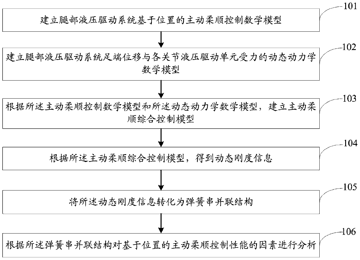
[0071] figure 1 It is a flow chart of the position-based active compliance control method of the present invention. Such as figure 1 As shown, a position-based active compliance control method, including:
[0072] Step 101: Establish a position-based active compliance control mathematical model of the leg hydraulic drive system, specifically including:
[0073] Establish the dynamic kinematics relationship matrix between the displacement of the foot end of the leg hydraulic drive system and the displacement of the hydraulic drive unit of each joint;
[0074] Establish the statics Jacobian matrix of the force at the foot end of the leg hydraulic drive system and the force of the hydraulic drive unit, and obtain the statics relationship matrix;
[0075] For each joint hydraulic drive unit of the leg hydraulic system, a position control system mathematical model is established, and the position control system mathematical model includes nonlinear factors;
[0076] According t...
Embodiment 2
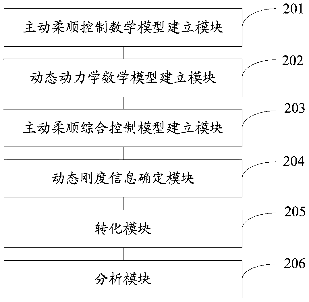
[0090] figure 2 It is a structural diagram of the position-based active compliance control system of the present invention. Such as figure 2 As shown, a position-based active compliance control system includes:
[0091] The active compliance control mathematical model building module 201 is used to establish a position-based active compliance control mathematical model of the leg hydraulic drive system;
[0092] The dynamic dynamics mathematical model building module 202 is used to establish the dynamic dynamics mathematical model of the displacement of the foot end of the hydraulic drive system of the leg and the force of the hydraulic drive unit of each joint;
[0093] An active compliance comprehensive control model building module 203, configured to establish an active compliance comprehensive control model according to the active compliance control mathematical model and the dynamic dynamics mathematical model;
[0094] A dynamic stiffness information determination m...
Embodiment 3
[0108] The present invention discloses the composition mechanism of dynamic stiffness control of the inner and outer loops based on the position-based active compliance control, and the specific content includes the following steps:
[0109] Step 1: Mathematical modeling of the active compliance control of the leg hydraulic drive system.
[0110] ①Establish the dynamic kinematics relationship matrix between the foot end displacement of the hydraulic drive system of the leg and the displacement of the hydraulic drive unit of each joint.
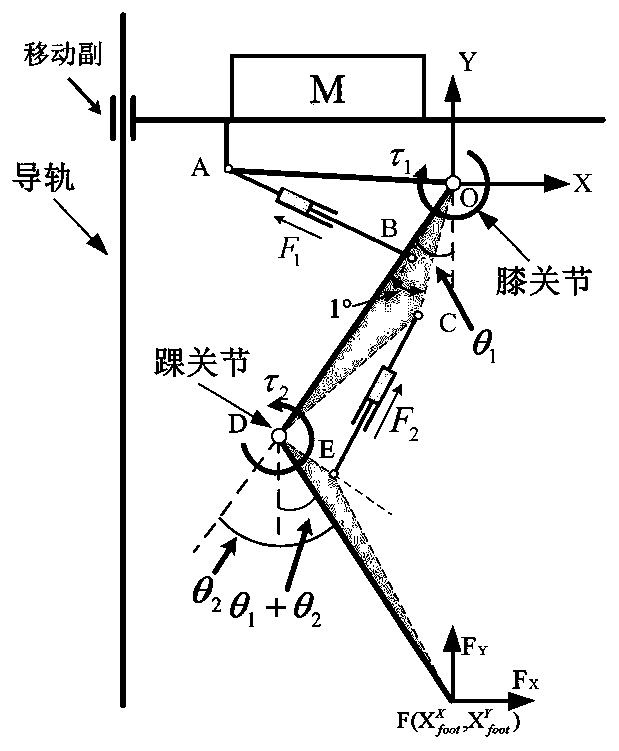
[0111] image 3 A schematic diagram of the leg kinematics of a legged robot, image 3 Among them, OA, OB, OC, OD, DE, DF, and EF are all known length parameters, and AB and CE are the lengths of the hydraulic drive unit of the knee joint and ankle joint, respectively, which change in real time with the movement of the robot.
[0112] When the position variation of the hydraulic drive unit of the knee joint and ankle joint is an independent v...
PUM
 Abstract
Description
Claims
Application Information
 - R&D
- Intellectual Property
- Life Sciences
- Materials
- Tech Scout
- Unparalleled Data Quality
- Higher Quality Content
- 60% Fewer Hallucinations
Browse by: Latest US Patents, China's latest patents, Technical Efficacy Thesaurus, Application Domain, Technology Topic, Popular Technical Reports.
© 2025 PatSnap. All rights reserved.Legal|Privacy policy|Modern Slavery Act Transparency Statement|Sitemap|About US| Contact US: help@patsnap.com