Hanging type straw bundling machine driven by single chain
A single-chain, strapping machine technology, applied in packaging, agricultural machinery and tools, applications, etc., can solve the problems of complex structure, inconvenient maintenance and installation, and high cost
- Summary
- Abstract
- Description
- Claims
- Application Information
AI Technical Summary
Problems solved by technology
Method used
Image
Examples
Embodiment 1
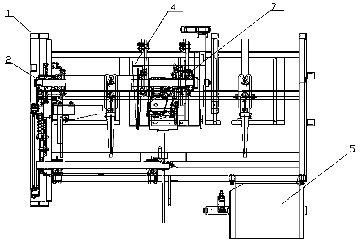
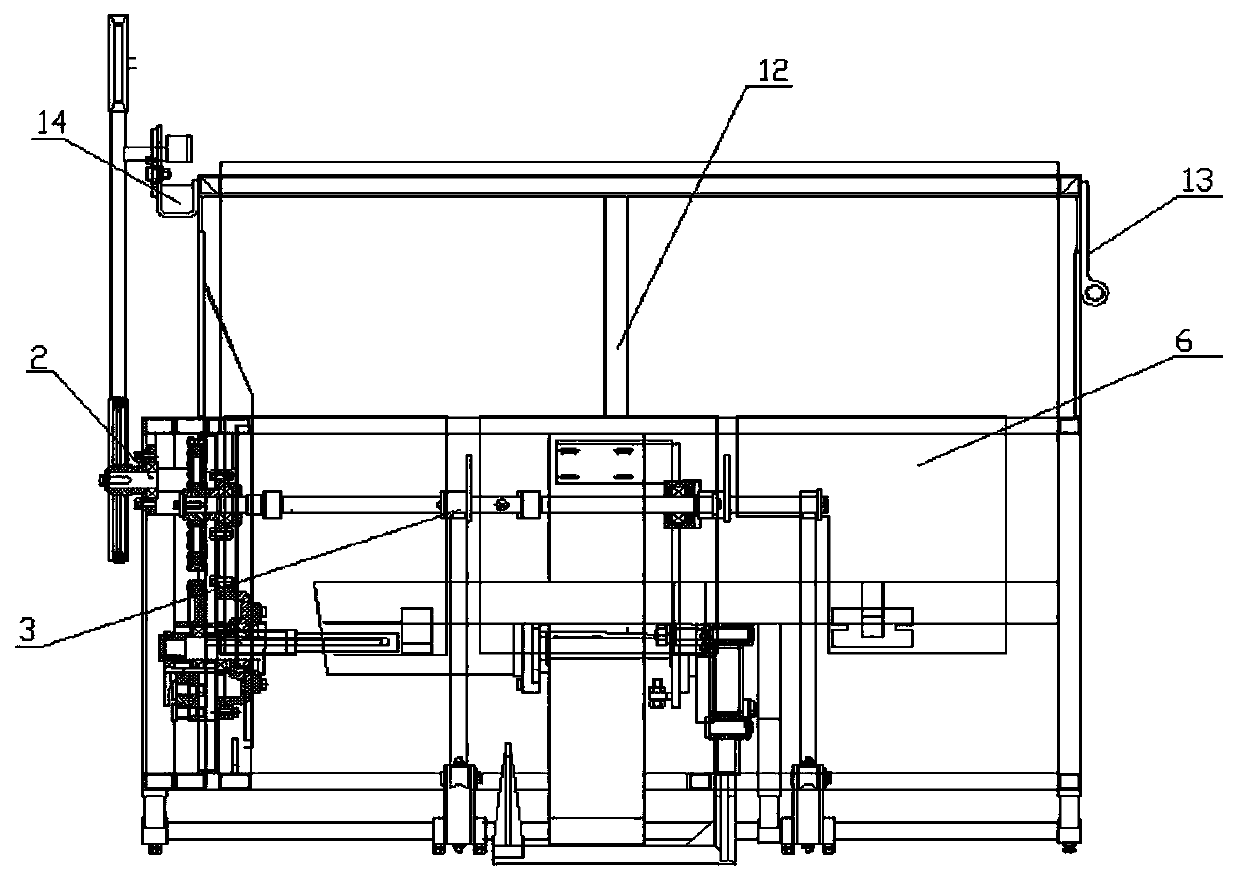
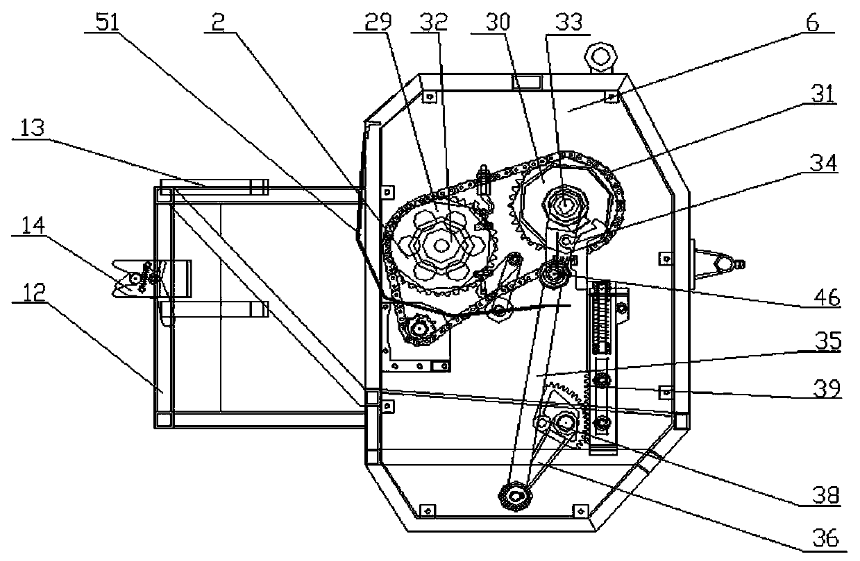
[0048] Such as figure 1 , figure 2 , image 3 , Figure 4 , Figure 5 , Image 6 , Figure 7 , Figure 8 , Figure 9 , Figure 10 , Figure 11 , Figure 12 , Figure 13 , Figure 14 , Figure 15 , Figure 21 , Figure 23As shown, a hanging straw baler driven by a single chain includes a frame body assembly 1, a transmission assembly 2, a grass feeding assembly 3, a grass blocking assembly 4, a rope storage assembly 5, and a baffle Assembly 6, knotted installation assembly 7, the frame body assembly 1 includes left frame 8, right frame 9, bracket 10, hanger 11, connecting frame 12, right reinforcing plate 13, left connecting plate 14, horizontal Bracket 15, described cross bracket 15 is welded and arranged between left frame 8 and right frame 9, is provided with a plurality of cross brackets 15 between described left frame 8 and right frame 9, and described hanger 11 is arranged on On the horizontal bracket 15 at the top, it is welded and connected with the hor...
Embodiment 2
[0050] Such as figure 1 , figure 2 , image 3 , Figure 4 , Figure 5 , Image 6 , Figure 19 , Figure 21 , Figure 23 As shown, the grass feeding assembly 3 is arranged in the middle of the frame body assembly 1, and the grass blocking and grass output assembly 4 is arranged at the front end of the grass feeding assembly 3 and is located at the front end of the frame body assembly 1. , the knotted installation assembly 7 is arranged between the grass-feeding assembly 3 and the grass-blocking and grass-out assembly 4, the baffle assembly 6 is arranged inside the frame body assembly 1, and the rope storage The assembly 5 is arranged on the lower right side of the front end of the frame body assembly 1 and is connected with the frame body assembly 1 by bolts 19 .
Embodiment 3
[0052] Such as figure 1 , figure 2 , image 3 , Figure 5 , Figure 16 , Figure 17 , Figure 18 , Figure 21 As shown, the grass feeding assembly 3 includes a grass feeding fork 48, a crank shaft 49 and a pull rod 50. The grass feeding fork 48 is arranged at the bottom of the rear end of the pulling rod 50, and a through hole is provided at the connection with the pulling rod 50. The pull rod 50 is arc-shaped, one end is welded to the grass fork 48, and the other end is connected to the frame body assembly 1 through a pin shaft. The grass fork 48 is arranged on the crank shaft 49 and connected to the crank shaft 49 socket connections, the described pitchfork 48 passes through the crankshaft 49 through the through hole and is connected on the crankshaft 49, and the described pitchfork 48 includes a left-feeding pitchfork and a right-feeding pitchfork. The right-advance grass fork is arranged on the right side of the left-advance grass fork, and the left-advance grass f...
PUM
 Abstract
Description
Claims
Application Information
 - R&D
- Intellectual Property
- Life Sciences
- Materials
- Tech Scout
- Unparalleled Data Quality
- Higher Quality Content
- 60% Fewer Hallucinations
Browse by: Latest US Patents, China's latest patents, Technical Efficacy Thesaurus, Application Domain, Technology Topic, Popular Technical Reports.
© 2025 PatSnap. All rights reserved.Legal|Privacy policy|Modern Slavery Act Transparency Statement|Sitemap|About US| Contact US: help@patsnap.com


