Steel pipe discharging packaging production line

A production line and cutting technology, applied in packaging and other directions, can solve the problems of increasing the operator's workload, unadjustable specifications, and increasing labor intensity, saving manpower, reducing labor intensity, and improving work efficiency.

Pending Publication Date: 2019-11-05
TIANJIN YOUFA STEEL PIPE GRP CO LTD +1
View PDF9 Cites 2 Cited by
  • Summary
  • Abstract
  • Description
  • Claims
  • Application Information

AI Technical Summary

Problems solved by technology

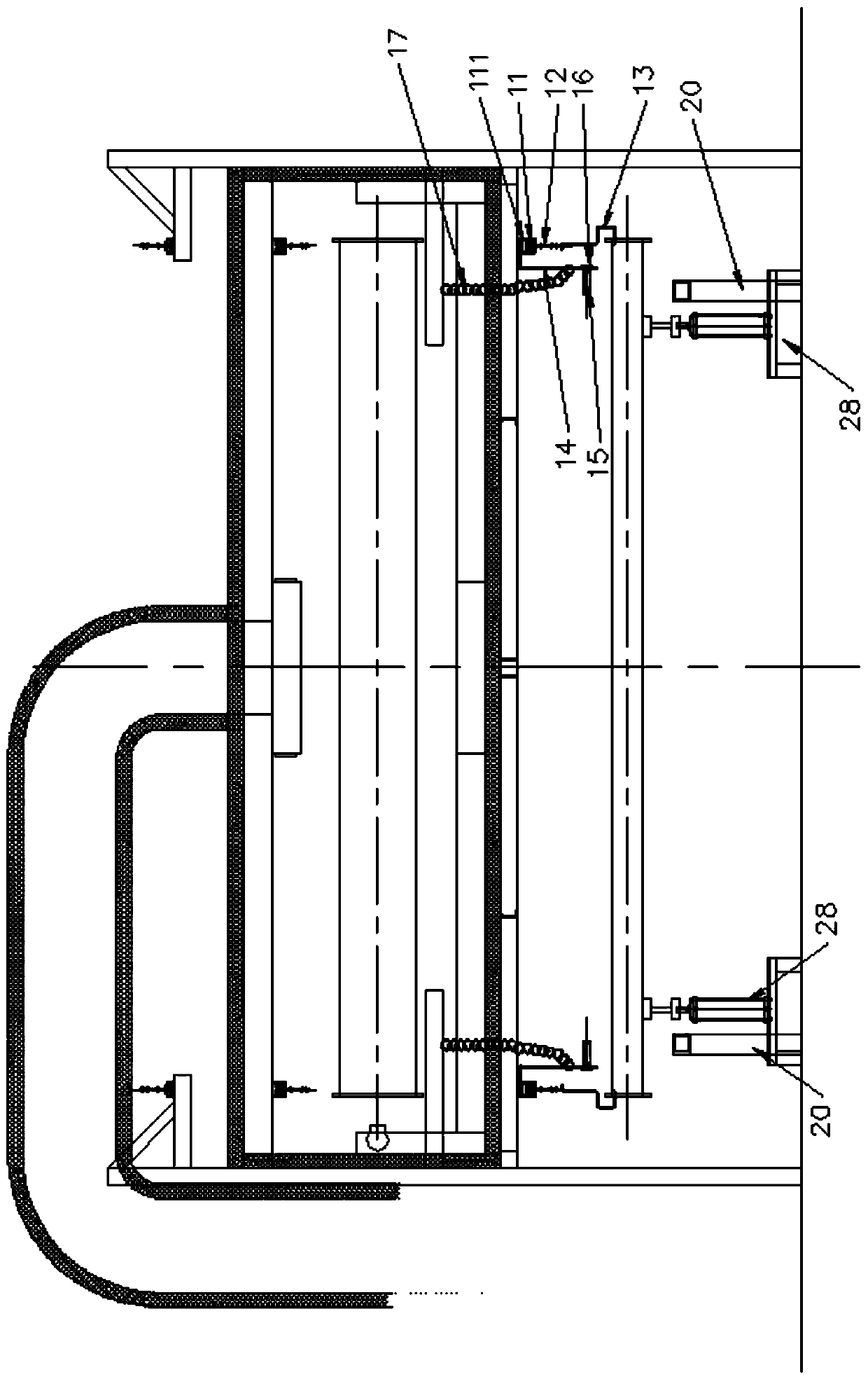
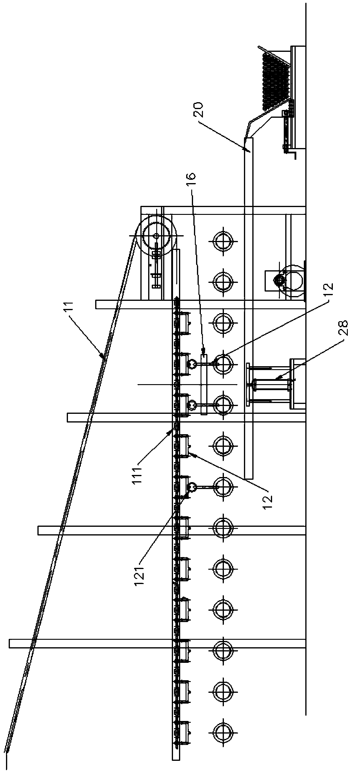
[0004] After the plastic-coated steel pipes are coated and dried, they are usually packaged directly to facilitate subsequent processes. The plastic-coating process is a production line with relatively large equipment, which can be applied to plastic-coating steel pipes of different specifications. At the back end of the plastic-coating production line, Set up the packaging device. From the plastic-coated air-dried conveyor chain to the packaging device, the traditional operations are all manual. Two operators need to be installed at both ends of the conveyor chain to remove the plastic-coated steel pipe from the hook. Many steel pipes are large and heavy, and the continuous operation is very labor-intensive. If shifts are used, the manpower will be greatly increased, and the cost of the enterprise will be increased. In addition, for different specifications, the number of packages is different. The current packaging device The specifications cannot be adjusted, and the packaging equipment needs to be replaced when packaging plastic-coated steel pipes of different specifications, which increases the workload of the operator to a certain extent, increases the labor intensity, and is troublesome to replace back and forth

Method used


Image

  • Steel pipe discharging packaging production line
  • Steel pipe discharging packaging production line
  • Steel pipe discharging packaging production line

Examples


Embodiment Construction

[0030] In order to make the above objects, features and advantages of the present invention more comprehensible, specific implementations of the present invention will be described in detail below in conjunction with the accompanying drawings.

[0031] In the following description, a lot of specific details are set forth in order to fully understand the present invention, but the present invention can also be implemented in other ways different from those described here, and those skilled in the art can do it without departing from the meaning of the present invention. By analogy, the present invention is therefore not limited to the specific examples disclosed below.

[0032] Secondly, the present invention is described in detail in combination with schematic diagrams. When describing the embodiments of the present invention in detail, for the convenience of explanation, the cross-sectional view showing the device structure will not be partially enlarged according to the gener...


PUM


Abstract

The invention discloses a steel pipe discharging packaging production line and belongs to the field of steel pipe discharging equipment. The steel pipe discharging packaging production line comprisesa conveying chain. Multiple hanging tools are arranged at the lower ends of the two sides of the conveying chain, and lifting hooks are arranged at the lower ends of the hanging tools. Steel pipes arehung at the lower ends of the lifting hooks, and packaging assemblies are arranged at the discharging end of the conveying chain. An unhooking assembly is arranged at the end, close to each packagingassembly, of the conveying chain. Each unhooking assembly comprises a rotating plate. The upper ends of the rotating plates are hinged to a fixing device of a production line, and the lower ends of the rotating plates are fixedly provided with unhooking air cylinders. Push plates are arranged on output shafts of the unhooking air cylinders, the push plates are arranged corresponding to the uppermiddle ends of the lifting hooks, the push plates are arranged on the inner sides of the lifting hooks, and the moving direction of the push plates is perpendicular to the side faces of the lifting hooks. By means of the steel pipe discharging packaging production line, automatic discharging of the steel pipes can be achieved, the labor intensity is lowered, and the work efficiency is improved.

Description

technical field [0001] The invention belongs to the field of packing steel pipes, and relates to a packing device for steel pipes used in a plastic coating production line, in particular to a steel pipe blanking and packing production line. Background technique [0002] Plastic-coated steel pipes, also known as plastic-coated pipes, steel-plastic composite pipes, and plastic-coated composite steel pipes, use steel pipes as the substrate, and weld a layer of plastic anti-corrosion layer or The steel-plastic composite steel pipe with plastic anti-corrosion layer welded on the inner and outer surfaces, the plastic-coated steel pipe has excellent corrosion resistance and relatively small frictional resistance, and the epoxy resin-coated steel pipe is suitable for water supply and drainage, sea water, warm water, oil, gas and other media For transportation, PVC-coated steel pipes are suitable for the transportation of drainage, sea water, oil, gas and other media. [0003] Plast...

Claims


Application Information

Patent Timeline
Patent Type & Authority Applications(China)
IPC IPC(8): B65B35/44B65B61/28
CPCB65B35/44B65B61/28
Inventor 李茂津陈广岭于红颖韩文堂张祥贵宋晓辉
Owner TIANJIN YOUFA STEEL PIPE GRP CO LTD
Why Eureka
Try Eureka