Steel rail damper

A damper and rail technology, applied in the field of rail dampers, can solve problems such as inconsistent natural frequency, poor vibration and noise reduction effects, and limited vibration absorption effect, and achieve improved vibration absorption bandwidth, simple clip structure, and improved vibration absorption efficiency effect

Pending Publication Date: 2019-11-05
洛阳双瑞橡塑科技有限公司
View PDF0 Cites 8 Cited by
  • Summary
  • Abstract
  • Description
  • Claims
  • Application Information

AI Technical Summary

Problems solved by technology

However, the rail damper with dynamic vibration absorber structure also has a fatal shortcoming: the damping frequency band of the rail damper is very narrow, and its natural frequency must be near the natural frequency of the rail. If the natural frequency of the rail damper is far away from the natural frequency of the rail, It will not be able to form an anti-resonance effect, and its "vibration absorption" effect will be very limited
The problem caused by different working conditions is that the natural frequencies of vibration of different rails are different.
If the same product is used on different lines, the natural frequency of the rail damper will be inconsistent with the natural frequency of the rail vibration, so it will be difficult to exert the vibration absorption effect of the rail damper
In addition, as the operating life of the line increases, the working condition parameters of the track will change (for example: after a long period of use, the elastic elements in the fasteners will age and their stiffness will change) which will also cause the natural frequency of vibration of the rail to change. The rail damper with matching natural frequency will no longer be applicable, and the effect of vibration and noise reduction will become worse

Method used


Image

  • Steel rail damper
  • Steel rail damper
  • Steel rail damper

Examples


Embodiment 1

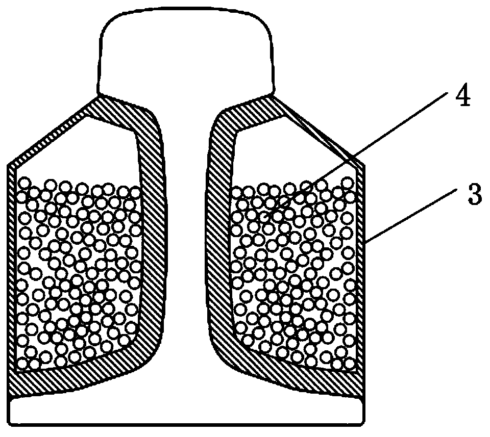
[0044] A rail damper such as figure 2 As shown, the damper 10 includes one or more cavity structures 3, the cavity structures 3 are arranged on both sides of the rail waist or above the rail bottom or below the rail bottom, and the cavity structure 2 is filled with a large number of discrete particles4.

[0045] The cavity structure 3 is arranged along the cross-sectional direction of the rail, or along the longitudinal direction of the rail.

[0046] The cavity structure 3 is set as a rigid structure, and the cavity structure 3 is in rigid contact with the rail.

[0047] The discrete particles 4 are one material or multiple materials, such as Figure 6 , the discrete particle 4 includes a first discrete particle 41 and a second discrete particle 42, the first discrete particle 41 and the second discrete particle 42 have the same or different particle sizes, that is, the discrete particle size is one or more .

[0048] The cavity structure 3 is closely attached to the rai...

Embodiment 2

[0053] This embodiment combines the principle of the traditional rail damper (the principle of the dynamic vibration absorber) of the first embodiment.

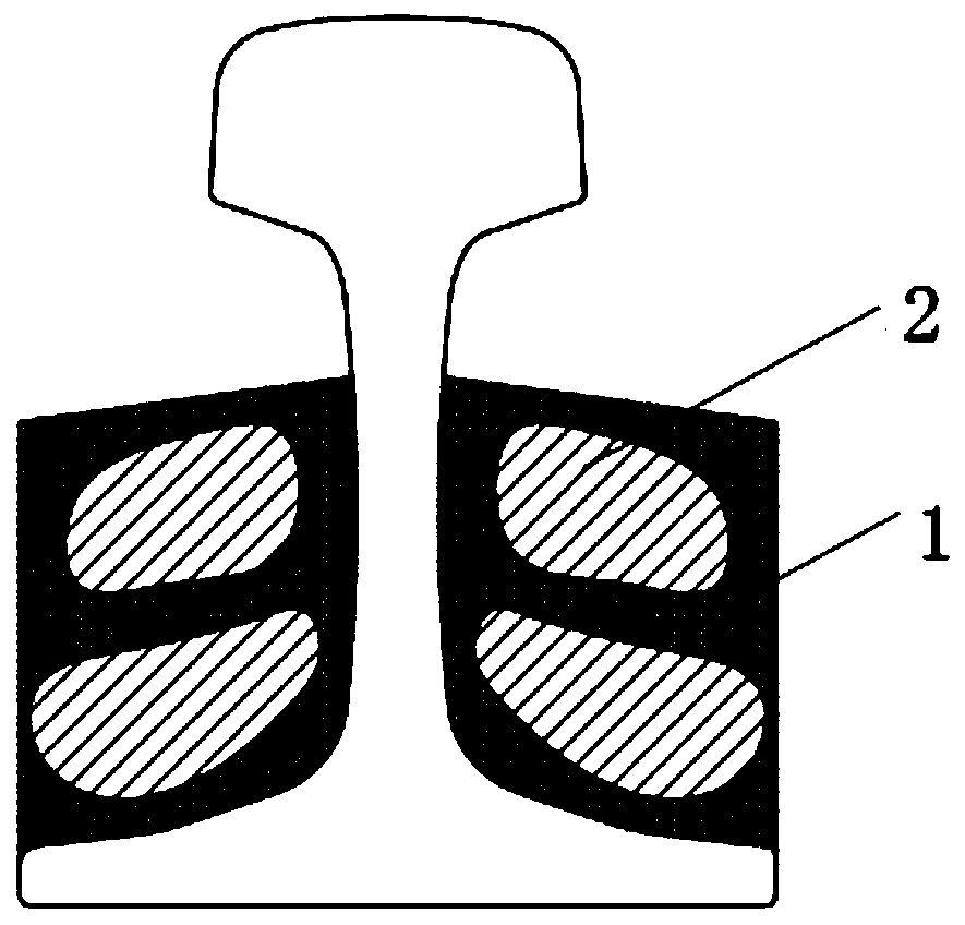
[0054] Such as Figure 4 As shown, the damper 10 in this embodiment includes an elastic damping unit 1 and a cavity structure 3 , and the cavity structure 3 is a cavity formed by the body of the elastic damping unit 1 .

[0055] Further, the cavity structure can also be a metal cavity. The elastic damping unit 1 and the cavity structure 3 are formed integrally, for example, by direct vulcanization.

[0056] Further, the cavity structure 3 is filled with discrete particles 4 .

[0057] In this embodiment, the mass unit of the traditional rail damper is changed to a structure 3 in which discrete particles fill the cavity. This structure applies the principle of a dynamic vibration absorber: the cavity structure 3 and discrete particles together constitute a mass unit, but the principle of particle damping is added on this ba...

Embodiment 3

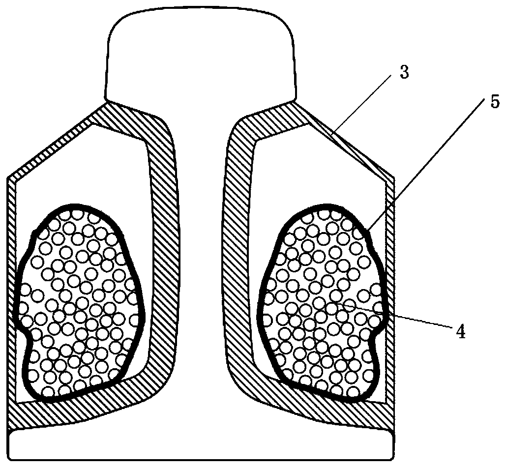
[0059] This scheme improves on the basis of embodiment two, as Figure 5 , the cavity structure 3 is provided with an opening 6, and the opening 6 is provided with a detachable cover. The openings 6 are arranged at the top and bottom of the cavity structure 3, so that the discrete particles 4 are added from the top opening, or the discrete particles 4 are reduced from the bottom opening. The total mass and particle size of the particles in the cavity structure 3 can be adjusted through the opening 6 . When high-speed discrete particles are required, open the cover of the corresponding opening for adjustment, and after the adjustment is completed, plug the opening and put it into use. There are one or more cavity openings 6 . The cavity opening 6 can be opened or closed, for example, by adopting a threaded structure, a plug structure, an elastic clamping structure, and the like.

[0060] Such as Figure 6 , the discrete particle material, density one or more, size one or mo...


PUM


Abstract

The invention discloses a steel rail damper. The damper includes at least one cavity structure; the cavity structures are provided with fillers; and the fillers can be fluidly arranged in the cavity structures. The damper can be commonly formed by the cavity structures and discrete particles, so that the damper can absorb the vibration of a steel rail through a principle of a dynamic vibration absorber and also can absorb the vibration of the steel rail through a principle of particle damping; and with the existence of particle damping, the vibration absorption efficiency and vibration absorption bandwidth of the damper can be enhanced, and better vibration absorption effects can be generated.

Description

technical field [0001] The invention belongs to the technical field of railway traffic, and specifically proposes a rail damper. Background technique [0002] Traditional rail dampers mostly use dynamic vibration absorber DVA (Dynamic Vibration Absorber) structure, such as figure 1 shown. Its main components include elastic-damping unit and mass unit. [0003] The principle of its use is: the natural frequency of the rail damper is close to or coincides with the natural frequency of the rail's own vibration. When the rail vibrates in a frequency band near its natural frequency, the "mass-spring-damping" system formed by the rail damper and the rail form a Reverse resonance, thereby reducing the vibration of the rail and absorbing the vibration energy of the rail. The advantage of using a dynamic vibration absorber structure rail damper is that it can be designed for a specific natural frequency of the rail, and the vibration absorption effect is good. In the best case, it...

Claims


Application Information

Patent Timeline
Patent Type & Authority Applications(China)
IPC IPC(8): E01B19/00E01B9/34
CPCE01B9/34E01B19/003
Inventor 樊永欣黄承张用兵尹旭超曾飞王金朝
Owner 洛阳双瑞橡塑科技有限公司
Why Eureka
Try Eureka