Boiler system with heat energy recovery function and heat energy recovery method of boiler system

A heat recovery and boiler technology, which is applied in the field of steam systems, can solve the problems of low temperature that cannot satisfy flue gas recovery, waste, and recovery heat efficiency, and achieve obvious energy saving effects, fuel saving, and fuel reduction effects

Pending Publication Date: 2019-11-05
苏明均
View PDF0 Cites 0 Cited by
  • Summary
  • Abstract
  • Description
  • Claims
  • Application Information

AI Technical Summary

Problems solved by technology

[0003] The prior art discloses a steam recovery and utilization system, which aims to solve the problem that water vapor is directly discharged into the air after heat exchange, causing waste. It includes a liquefaction pipe, a cooling pipe, a cooling water tank, and a recovery water tank, wherein the top of the liquefaction pipe extends upwards and communicates with another water recovery device; the cooling water tank communicates with the heat storage water tank and a first recovery electric valve is arranged between the two, There is also a temperature sensor in the cooling water tank, and the first recovery electric valve is coupled to the temperature sensor; the recovery water tank is connected to the heat storage water tank, and a second recovery electric valve is arranged between them, and the first water level sensor is installed in the recovery water tank , the first water level sensor is coupled with the second recovery electric valve
[0004] However, the above-mentioned steam recovery and utilization system needs to liquefy the steam, and the temperature of the heat recovery effect is low, which cannot meet the recovery of a large amount of flue gas produced by large steam boilers.

Method used


Image

  • Boiler system with heat energy recovery function and heat energy recovery method of boiler system
  • Boiler system with heat energy recovery function and heat energy recovery method of boiler system
  • Boiler system with heat energy recovery function and heat energy recovery method of boiler system

Examples


Embodiment Construction

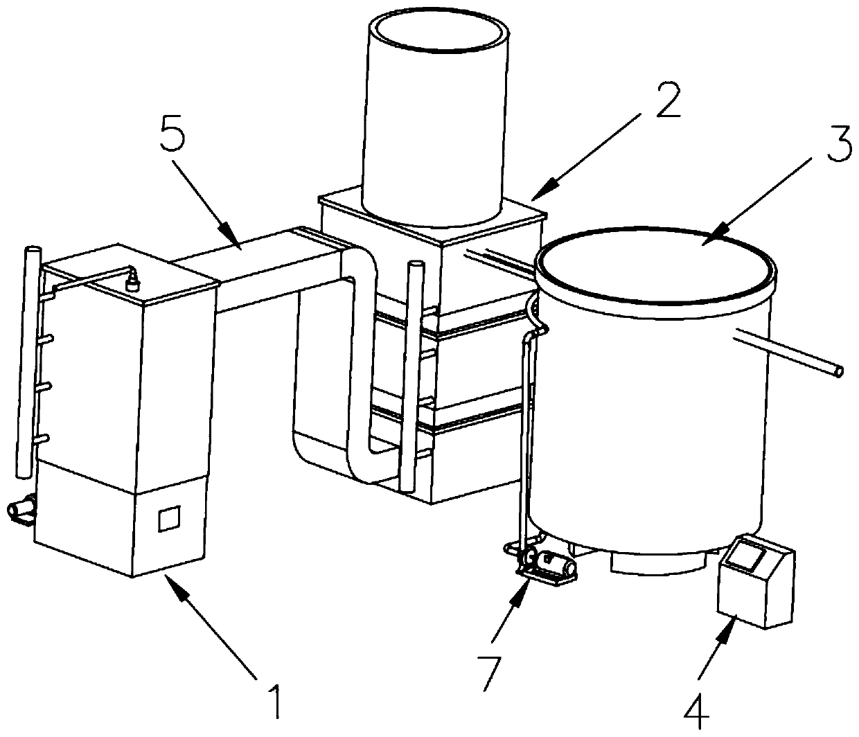
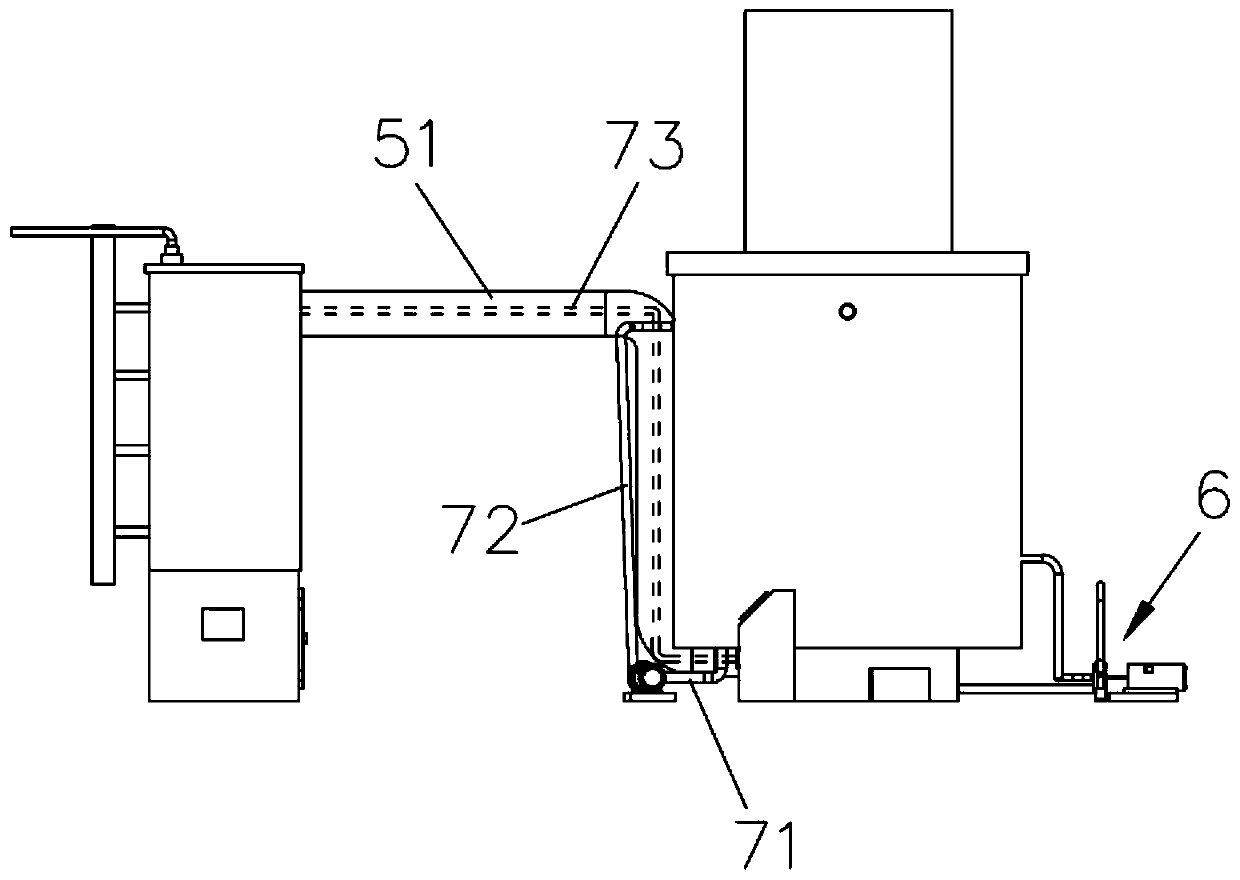
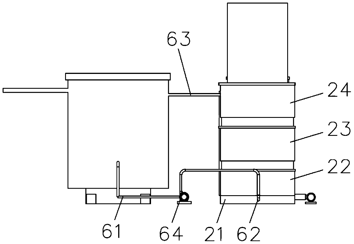
[0026] Attached below Figures 1 to 7 The present invention will be described in detail.

[0027] A boiler system with heat energy recovery of the present invention includes a boiler assembly 1, a heat energy recovery assembly 2, a water storage device 3 and a control device 4, the water storage device 3 includes a base and a water storage device arranged above the base tank, a water temperature sensor is installed in the water storage tank. The boiler assembly 1 is connected with a flue device 5, and the flue device 5 is connected with the heat energy recovery assembly 2; the heat energy recovery assembly 2 is provided with a The chimney, the water storage device 3 is connected with a first pump circulation device 6, the first pump circulation device 6 transports water to the heat energy recovery assembly 2, and the heat energy recovery assembly 2 circulates the heated water back to the water storage device 3; The water storage device 3 is also connected with a second pumpin...


PUM


Abstract

The invention relates to the technical field of steam systems, and discloses a boiler system with a heat energy recovery function. The boiler system comprises a boiler assembly, and further comprisesa heat energy recovery assembly, a water storage device and a control device, and the boiler assembly is connected with a flue device. According to the boiler system, flue gas heat energy is recoveredby a heat exchange tube, then water which has been heated is delivered to the boiler assembly from the inside of the flue device through a second pumping device, thus, fuels for heating a boiler is reduced, the fuels are saved by 35% or above, and the heat efficiency recovery rate is high. The invention also provides a heat energy recovery method of the boiler, in the recovery method, heat energyis recovered in a mode that recovery heat pipes distributed along a flue gas channel are opposite to flue gas emission, so that the flue gas at high temperature with high heat can be recovered to themaximum extent, the flue gas emission temperature is lower than 100 DEG C, and the energy-saving effect is obvious.

Description

technical field [0001] The invention relates to the technical field of steam systems, in particular to a boiler system with heat energy recovery and a heat energy recovery method thereof. Background technique [0002] Although human beings have used steam for several years, steam is still an indispensable energy source in modern industry. For example, in industries such as papermaking, clothing, printing and dyeing, a large number of production activities rely on steam. [0003] The prior art discloses a steam recovery and utilization system, which aims to solve the problem that water vapor is directly discharged into the air after heat exchange, causing waste. It includes a liquefaction pipe, a cooling pipe, a cooling water tank, and a recovery water tank, wherein the top of the liquefaction pipe extends upwards and communicates with another water recovery device; the cooling water tank communicates with the heat storage water tank and a first recovery electric valve is arr...

Claims


Application Information

Patent Timeline
Patent Type & Authority Applications(China)
IPC IPC(8): F22B31/08F22D1/00F22B37/00
CPCF22B31/08F22B37/008F22D1/003
Inventor 苏明均
Owner 苏明均
Why Eureka
Try Eureka