Catalytic combustion all-in-one machine

A catalytic combustion, all-in-one technology, applied in the combustion method, combustion type, incinerator and other directions, can solve the problems of high cost and complex structure of the catalytic combustion device, and achieve the effects of low manufacturing and processing cost, easy handling and installation, and improved efficiency.

Pending Publication Date: 2019-11-05
SHANDONG HOLONE ENVIRONMENT TECH
View PDF0 Cites 1 Cited by
  • Summary
  • Abstract
  • Description
  • Claims
  • Application Information

AI Technical Summary

Problems solved by technology

[0009] The invention proposes a catalytic combustion integrated machine, which solves the problems of complex structure and high cost of catalytic combustion devices in the prior art

Method used


Image

  • Catalytic combustion all-in-one machine
  • Catalytic combustion all-in-one machine

Examples


Embodiment

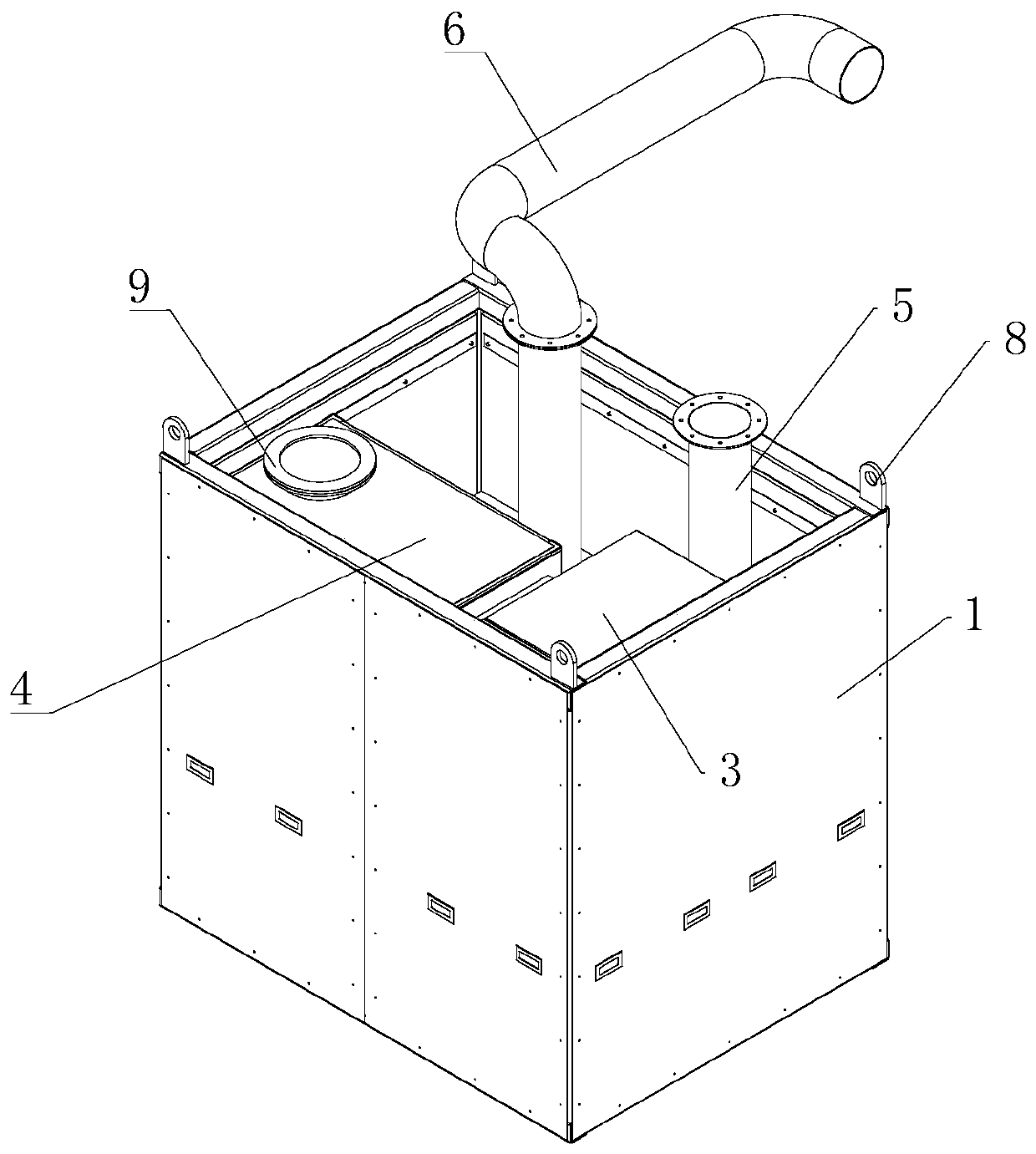
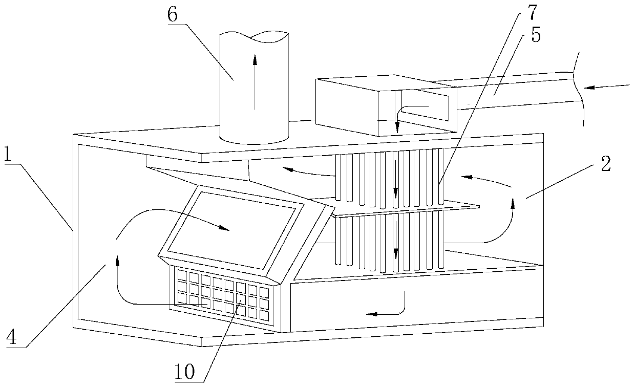
[0031] Such as figure 1 with figure 2 As shown, they are the structural diagram and schematic diagram of the catalytic combustion integrated machine of the present invention, respectively. The integrated machine first includes a body shell 1, and a body heat exchange chamber 2, an electric heating chamber 3, and a catalytic combustion chamber 4 are arranged inside the body shell 1. , and the exhaust gas inlet 5 and the gas outlet 6 are also connected to the body shell 1 at the same time. The basic working principle of this all-in-one machine is: the exhaust gas to be treated enters from the exhaust gas inlet 5, and then passes through the body heat exchange chamber 2 and the electric heating chamber 3 in turn, and the exhaust gas in the body heat exchange chamber 2 and electric heating chamber 3 can absorb heat to achieve Preheat, increase its temperature, and prepare for the subsequent catalytic combustion. After that, the waste gas enters the catalytic combustion chamber ...


PUM


Abstract

The invention provides a catalytic combustion all-in-one machine. The problems that in the prior art, a catalytic combustion device is complex in structure and high in cost are solved. The catalytic combustion all-in-one machine comprises a machine body shell, wherein a machine body heat exchange chamber, an electric heating chamber and a catalytic combustion chamber are arranged in the machine body shell, and a waste gas inlet and a gas outlet are further connected to the machine body shell; and waste gas entering from the waste gas inlet sequentially passes through the machine body heat exchange chamber, the electric heating chamber and the catalytic combustion chamber, the waste gas at the body heat exchange chamber and the electric heating chamber absorbs heat to achieve preheating, the waste gas at the catalytic combustion chamber is subjected to chemical reaction to generate high-temperature gas, the high-temperature gas passes through the machine body heat exchange chamber and is discharged out of the machine body shell from the gas outlet, and the high-temperature gas in the machine body heat exchange chamber is isolated from the waste gas and exchanges the heat.

Description

technical field [0001] The invention relates to the technical field of waste gas treatment equipment, in particular to a catalytic combustion integrated machine with simple structure and convenient use. Background technique [0002] The traditional working process of environmental protection equipment is that the exhaust gas enters the concentration runner after passing through the filter, and then passes through the cycle of concentration runner, heat exchanger and regenerative catalytic combustion to realize the heat treatment and purification of the exhaust gas. The regenerative catalytic combustion equipment realizes heat storage, purge, and heat release through the action cycle of the rotary valve, so that each heat storage area realizes the heat storage-heat release-cleaning process in turn, and the cycle continues to work to realize cycle purification. [0003] There are many shortcomings in the existing regenerative combustion device, as follows: [0004] 1) The col...

Claims


Application Information

Patent Timeline
Patent Type & Authority Applications(China)
IPC IPC(8): F23G7/07F23G5/46F23G5/50
CPCF23G5/46F23G5/50F23G7/07F23G2206/10
Inventor 张文海王建亮段元珍袁鸿臣李艳强
Owner SHANDONG HOLONE ENVIRONMENT TECH
Why Eureka
Try Eureka