
Ultrafast time domain stretching imaging device and method

A technology of an imaging device and an imaging method, which can be applied to measurement devices, instruments, scientific instruments, etc., and can solve problems such as difficult operation and large transmission loss of optical pulses.

Inactive Publication Date: 2019-11-05
WUHAN UNIV
View PDF5 Cites 6 Cited by
  • Summary
  • Abstract
  • Description
  • Claims
  • Application Information

AI Technical Summary

Problems solved by technology

[0005] The embodiment of the present application provides an ultra-fast time-domain stretching imaging device and method, which solves the problem of large optical pulse transmission loss and relatively difficult operation of the time-domain stretching-based ultra-fast imaging device in the prior art. The problem

Method used


Image

  • Ultrafast time domain stretching imaging device and method

Examples


Embodiment Construction

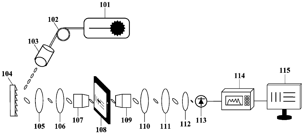
[0027] This embodiment provides an ultrafast time-domain stretch imaging device, which mainly includes: a femtosecond laser, a single-mode optical fiber, a diffraction grating, a first microscopic objective lens, a second microscopic objective lens, a third plano-convex lens, and a fourth plano-convex lens. Convex lens, fifth plano-convex lens, high-speed free-space photodetector, high-speed oscilloscope.

[0028] Wherein, the femtosecond laser is connected to the single-mode fiber, the diffraction grating is located between the single-mode fiber and the first microscope objective, and the observation object is located between the first microscope objective and the first microscope. Between the two microscopic objective lenses, the third plano-convex lens is placed in front of the second microscopic objective lens, the fourth plano-convex lens is placed in front of the third microscopic objective lens, and the fifth plano-convex lens is placed in front of the second microscopic...


PUM


Abstract

The invention discloses an ultrafast time domain stretching imaging device and method, and belongs to the technical field of high speed imaging. Plano-convex lenses are used to change the gathering size and angle of spatial coded pulses in a space in front of a fifth plano-convex lens, the fifth plano-convex lens further gathers light spots into an effective light reception range of a high-speed free space photoelectric detector, and the problem that a time domain stretching based ultrafast imaging device in the prior art has high light pulse transmission loss and is difficult in operation issolved. The imaging device and method of the invention is simple in operation and lower in light transmission loss, can effectively improve the signal to noise ratio of a corresponding system and achieve higher image quality.

Description

technical field [0001] The invention relates to the technical field of high-speed imaging, in particular to an ultrafast time-domain stretch imaging device and method. Background technique [0002] High-speed imaging has become a research hotspot and has attracted extensive attention. More and more fields such as laser ablation, neural activity, and intracellular chemical reactions require ultra-high imaging frame rates to meet the requirements of temporal resolution. At present, CCD and CMOS are the most commonly used tools for observing fast events. They have been developed rapidly, and the imaging frame rate can reach 1MHz, but they still cannot meet the needs of many applications. For scientific research, pump-probe technology with picosecond or even femtosecond time resolution is usually used, but it can only observe repeatable events but not one-time or non-repeatable events, such as optical shock waves. Detecting such events requires a fast, real-time, continuous ima...

Claims


Application Information

Patent Timeline
Patent Type & Authority Applications(China)
IPC IPC(8): G01N21/25
CPCG01N21/255
Inventor 雷诚刘胜翁跃云
Owner WUHAN UNIV
Learn More