
Analysis system for methane and non-methane total hydrocarbons and analysis method thereof

A non-methane total hydrocarbon and analysis system technology, applied in the detection field of carbon-containing compounds, can solve the problems of inability to achieve continuous analysis, complex instruments and equipment, and inability to obtain methane content

Active Publication Date: 2019-11-05
BEIJING SDL TECH
View PDF6 Cites 2 Cited by
  • Summary
  • Abstract
  • Description
  • Claims
  • Application Information

AI Technical Summary

Problems solved by technology

In order to achieve the purpose of enriching low-carbon, the method of freezing with low-temperature liquid inert gas (not using liquid nitrogen to prevent condensation of oxygen and methane) is used to remove methane, nitrogen, and oxygen. Although this method completely eliminates the interference of oxygen, it can Directly measure the results of non-methane total hydrocarbons, but cannot get the content of methane
Moreover, the equipment is too complicated, and the operation and calibration process is cumbersome, so continuous analysis cannot be realized. In addition, when the humidity of the sample gas is relatively high, the enrichment tube will freeze and affect the enrichment effect.

Method used


Image

  • Analysis system for methane and non-methane total hydrocarbons and analysis method thereof
  • Analysis system for methane and non-methane total hydrocarbons and analysis method thereof
  • Analysis system for methane and non-methane total hydrocarbons and analysis method thereof

Examples


Embodiment 1

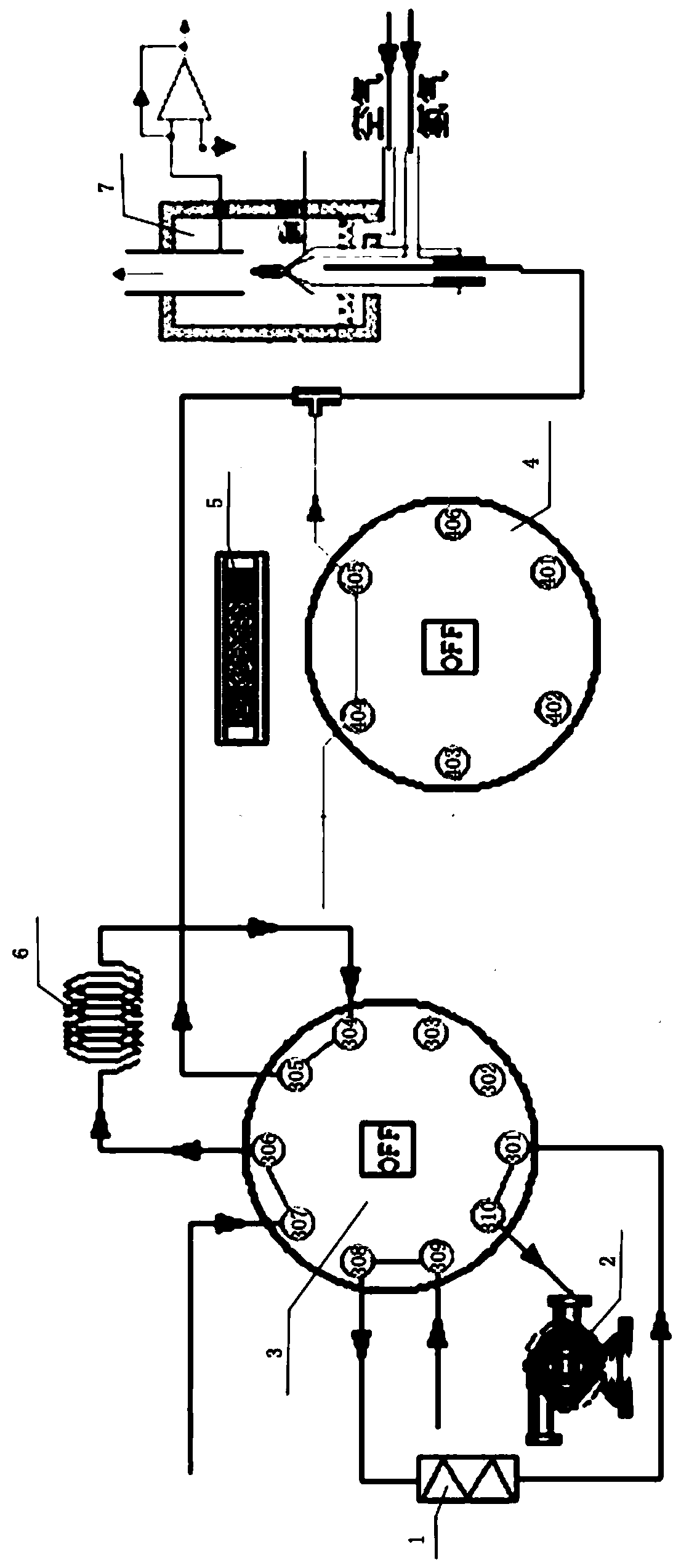
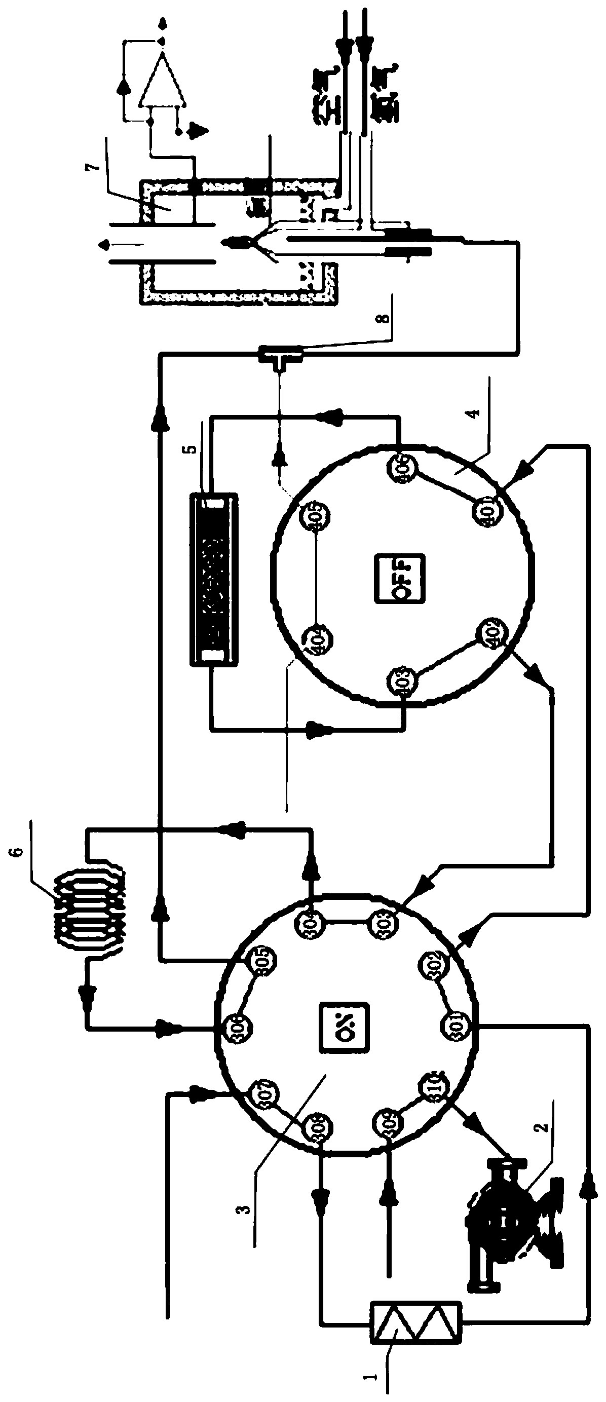
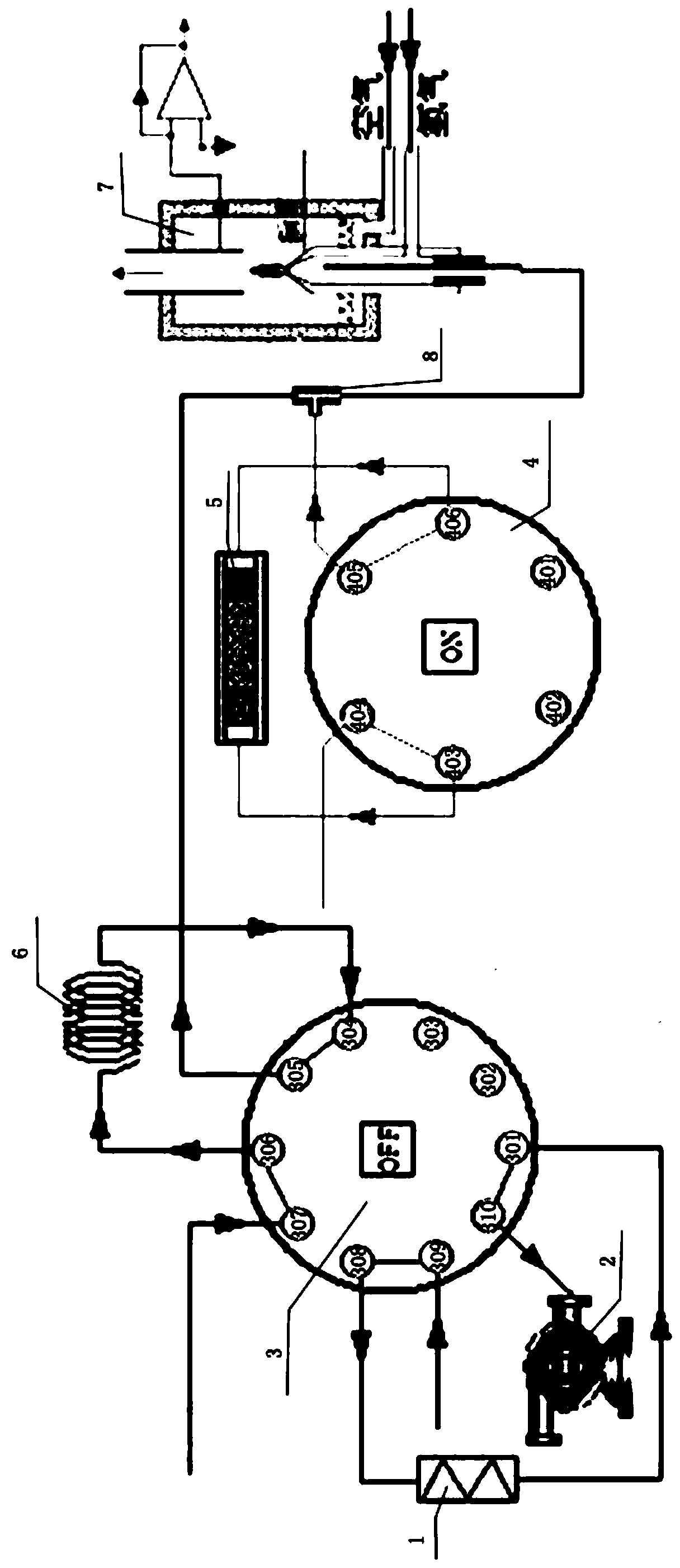
[0086] use Figure 1-3 The analysis system shown performs sample gas analysis. Among them, the low-carbon separation unit is a stainless steel column with a length of 1.5m and an inner diameter of 4mm, and the column is filled with 60-80 mesh GDX-502 polymer beads; the high-carbon adsorption unit is composed of a quartz glass tube with a length of 8cm and an inner diameter of 1.5mm, and the outer layer is wound with platinum. Heating wire, the tube is filled with 60-80 mesh graphitized carbon black Carbotrap B filler.

[0087] Analysis methods include:

[0088] 1. Sampling;

[0089] 2. For sample injection, the heating temperature for the low-carbon separation unit is 80°C;

[0090] 3. Low-carbon total hydrocarbons are backflushed, and the heating temperature for the low-carbon separation unit is 80°C;

[0091] 4. High-carbon total hydrocarbons are stored, and the heating temperature for the high-carbon adsorption unit is 240°C;

[0092] 5. High-carbon total hydrocarbons ...

Embodiment 2

[0098] use Figure 1-3 The analysis system shown performs sample gas analysis. Among them, the low-carbon separation unit is a stainless steel column with a length of 1.5m and an inner diameter of 4mm, and the column is filled with 60-80 mesh GDX-502 polymer beads; the high-carbon adsorption unit is made of a quartz glass tube with a length of 8cm and an inner diameter of 1.5mm, and the outer layer is wound with platinum. Heating wire, the tube is filled with 60-80 mesh graphitized carbon black Carbotrap B filler.

[0099] Analysis methods include:

[0100] 1. Sampling;

[0101] 2. For sample injection, the heating temperature for the low-carbon separation unit is 80°C;

[0102] 3. Low-carbon total hydrocarbons are backflushed, and the heating temperature for the low-carbon separation unit is 80°C;

[0103] 4. High-carbon total hydrocarbons are stored, and the heating temperature for the high-carbon adsorption unit is 240°C;

[0104] 5. High-carbon total hydrocarbons are ...


PUM


Abstract

The invention relates to an analysis system for methane and non-methane total hydrocarbons and an analysis method thereof. The analysis system comprises a multi-channel injection valve, a quantitativetube, an air suction pump, a high carbon adsorption unit, a low carbon separation unit and a hydrogen flame ionization detector; the analysis system forms a first state, a second state and a third state which are all switchable through the multi-channel injection valve. The analysis system can achieve the purpose of continuously and accurately analyzing and detecting the methane and non-methane total hydrocarbons completely without oxygen interference.

Description

technical field [0001] The present invention generally relates to the detection of carbon-containing compounds, in particular to an analysis system and analysis method for methane and non-methane total hydrocarbons. Background technique [0002] In environmental pollution monitoring, the monitoring of volatile organic compounds (VOCs) is generally divided into two categories: total monitoring and characteristic factor monitoring. Among them, total amount monitoring mainly uses total volatile organic compounds (TVOC) and non-methane total hydrocarbons (NMHC) as environmental control evaluation indicators. [0003] Total hydrocarbons, in the relevant environmental protection standards "HJ 604-2017 Determination of Total Hydrocarbons, Methane and Non-methane Total Hydrocarbons in Ambient Air Direct Sampling-Gas Chromatography" and "HJ 38-2017 Total Determination of hydrocarbons in "Gas Chromatography" is defined as "the sum of gaseous organic compounds responding on the hydrog...

Claims


Application Information

Patent Timeline
IPC IPC(8): G01N30/68G01N30/06
CPCG01N30/06G01N30/68
Inventor 敖小强张云张英平孙焕斌
Owner BEIJING SDL TECH
Learn More