
Multifunctional composite island power cable and manufacturing process thereof

A power cable and multi-functional technology, which is applied in the field of multi-functional composite island power cables and its manufacturing process, can solve the problems of damaged cables, excellent water resistance, and low cost, and achieve reduced electromagnetic conversion loss and heat generation, and good tensile strength Performance, the effect of reducing the difficulty of laying

Pending Publication Date: 2019-11-05
圣安电缆有限公司 +1
View PDF0 Cites 0 Cited by
  • Summary
  • Abstract
  • Description
  • Claims
  • Application Information

AI Technical Summary

Problems solved by technology

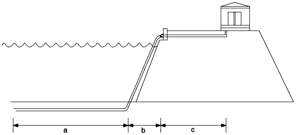
[0005] The purpose of the present invention is to provide a multifunctional composite island power cable and its manufacturing process, which solves the problem that the existing submarine cables are generally divided into underwater buried sections and land buried sections. The cable is damaged due to too small bending radius or too large tension, and the safety performance of existing cables is uneven, and it cannot achieve high conductivity, low cost, energy saving and environmental protection, excellent water resistance, corrosion resistance, creep resistance, fatigue resistance, etc. A variety of performance problems, so that according to the different laying environments of direct burial under the seabed, suspension of the coast section, and direct burial of the island land section, one cable design is segmented and differentiated structural design, which meets the requirements of different laying environments and has good performance. Waterproof, anti-corrosion, anti-ultraviolet, anti-oil and other properties, but also can reduce the magnetic flux of the outer layer of the cable, thereby reducing the electromagnetic conversion loss and heat generation in the process of cable power transmission

Method used


Image

  • Multifunctional composite island power cable and manufacturing process thereof
  • Multifunctional composite island power cable and manufacturing process thereof
  • Multifunctional composite island power cable and manufacturing process thereof

Examples


Embodiment Construction

[0056] In order to make the purpose, technical solutions and advantages of the embodiments of the present invention clearer, the technical solutions in the embodiments of the present invention will be clearly and completely described below in conjunction with the drawings in the embodiments of the present invention. Obviously, the described embodiments It is a part of embodiments of the present invention, but not all embodiments. The components of the embodiments of the invention generally described and illustrated in the figures herein may be arranged and designed in a variety of different configurations.

[0057] Accordingly, the following detailed description of the embodiments of the invention provided in the accompanying drawings is not intended to limit the scope of the claimed invention, but merely represents selected embodiments of the invention. Based on the embodiments of the present invention, all other embodiments obtained by persons of ordinary skill in the art wi...


PUM


Abstract

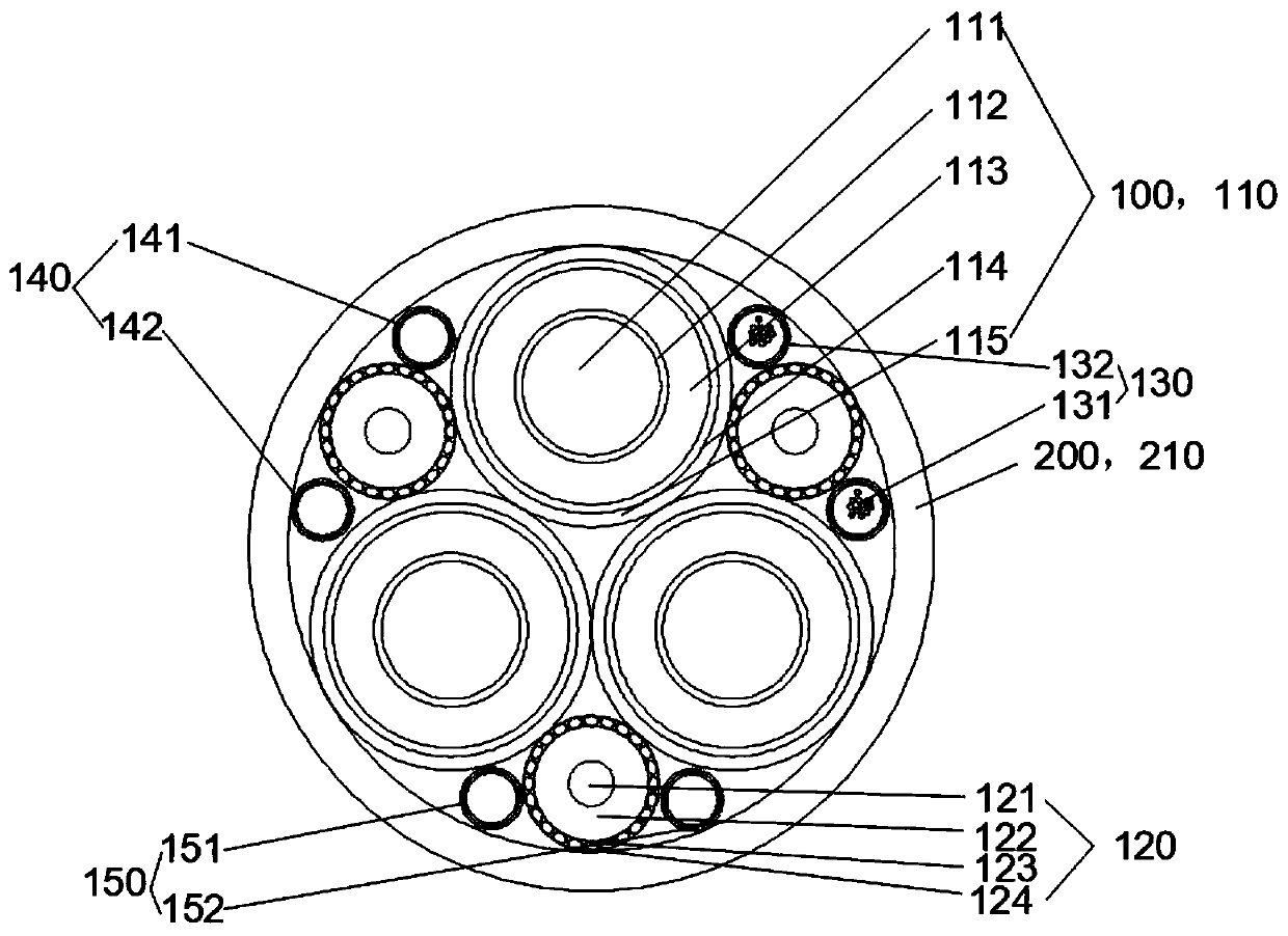
The invention discloses a multifunctional composite island power cable and a manufacturing process thereof. The power cable includes a seabed direct burial section, a land direct burial section, and acoast suspension section which communicates the seabed direct burial section with the land direct burial section. The power cable also includes a cable core and a protective layer arranged outside the cable core. The cable core includes at least one insulated wire core and at least one buffer tensile unit. According to the different laying environments for direct burial under the seabed, coastalsuspension and direct burial in the land section of an island, the cable is divided into three different protective structures of the land direct burial section, the coast suspension section and the seabed direct burial section. Through the sectional differential structure design of one cable, the requirements of different laying environments are met, the adaptability of the cable under differentenvironments is improved, and the cable is tensile, compressive, shock-resistant, vibration-resistant, waterproof, oil-proof, ultraviolet-proof and insect / rat-proof. The buffer tensile units have buffering and bearing effects under the action of short-time super-strength impact tension.

Description

technical field [0001] The invention relates to a multi-functional composite island power cable which is resistant to tension, compression, impact, shock, water, oil, ultraviolet rays and insects and rodents and its manufacturing process. Background technique [0002] my country is a large oceanic country with a sea area of ​​more than 3 million square kilometers and a coastline of 18,000 kilometers. There are more than 6,000 islands along the coast. There are rich submarine oil fields and natural gas in the shallow sea continental shelf. The coast is also an economically developed area in my country. The development of coastal islands urgently needs electricity. Due to the high cost and long period of construction of power stations, and the difficulty of fuel supply, etc., power supply and communication (especially military confidential communication) for small and medium-sized islands need to pass through long-length photoelectric integrated cables. To solve, so the cable is...

Claims


Application Information

Patent Timeline
Patent Type & Authority Applications(China)
IPC IPC(8): H01B7/18H01B7/22H01B7/24H01B7/26H01B7/28H01B7/282H01B9/00H01B3/26H01B3/48H01B7/02H01B13/22
CPCH01B7/1875H01B7/0208H01B7/24H01B7/225H01B3/26H01B7/26H01B7/2825H01B7/2806H01B13/22H01B3/48H01B9/003Y02A30/14
Inventor 蒋国君陆正荣唐芸周彩霞
Owner 圣安电缆有限公司
Learn More