Magnetic controllable reactor core structure and design method

A magnetically controlled reactor and iron core structure technology, which is applied in the fields of magnetic core manufacturing, transformer/inductor magnetic core, inductor/transformer/magnet manufacturing, etc. Satisfaction and other issues, to achieve the effect of small high-order harmonic content and reduce high-order harmonic components

Inactive Publication Date: 2019-11-05
李晓明
View PDF3 Cites 2 Cited by
  • Summary
  • Abstract
  • Description
  • Claims
  • Application Information

AI Technical Summary

Problems solved by technology

[0006] However, according to the inventor's understanding, the setting method and principle of the magnetic valve of the magnetic control reactor are often only based on experience, and the performance of the magnetic control reactor produced by different manufacturers is quite different, and the performance is not satisfactory.

Method used


Image

  • Magnetic controllable reactor core structure and design method
  • Magnetic controllable reactor core structure and design method

Examples


Embodiment 1

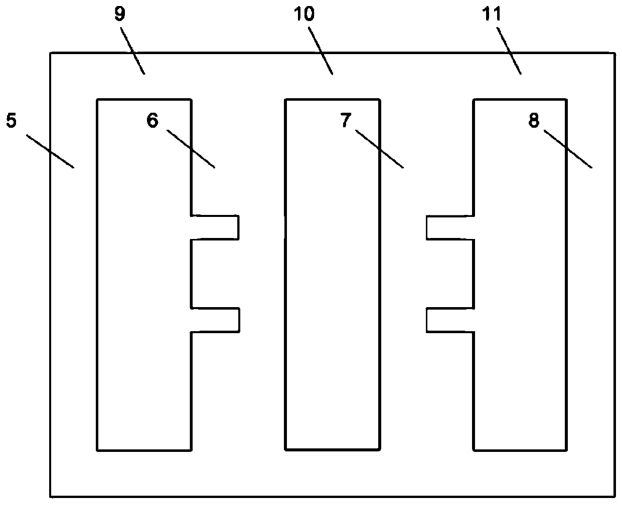
[0034] Such as figure 1 As shown, the magnetically controlled reactor core, the AC magnetic flux generated by the coil on the coil core column I6 circulates in the closed-loop core magnetic circuit formed by the coil core column I6, the AC iron core column I5, and the AC side yoke I9. The AC magnetic flux generated by the coil on the coil core post II7 circulates in the closed-loop core magnetic circuit formed by the coil core post II7, the AC core post II8 and the AC side yoke II11. The DC magnetic flux generated by the coil on the coil core post I6 and the coil core post II7 circulates in the closed-loop core magnetic circuit formed by the coil core post I6, the coil core post II7 and the DC core post 10. Magnetic valves are arranged on the coil iron core post I6 and the coil iron core post II7.

[0035] For the specific reactor coil structure, please refer to CN106026813A. Or select other existing structures, which will not be repeated here.

[0036] The cross-sectional ...

Embodiment 2

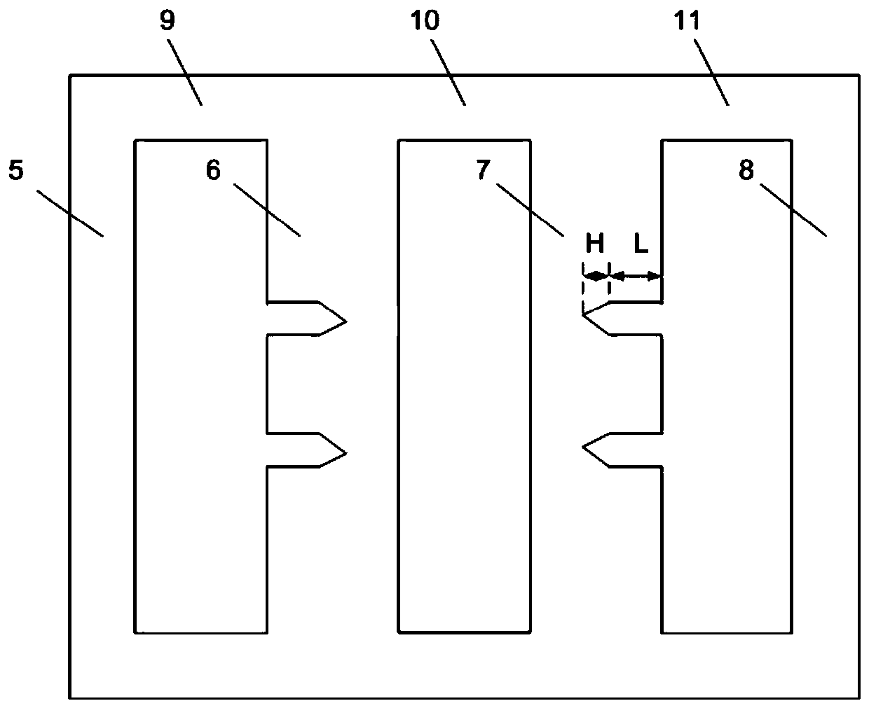
[0047] The magnetic valves on the coil iron core post I and the coil iron core post II are a combination of a rectangle and an isosceles triangle. The rectangular depth of the magnetic valve on the coil core post I and the coil core post II is L, the height of the isosceles triangle is H, and (L / H) is greater than 3 and less than 10. The magnetic valve of this embodiment is a combination of a rectangle and an isosceles triangle. The non-magnetic valve iron core and the magnetic valve transition through an isosceles triangle, which can reduce the ratio of harmonics to fundamental waves in other current states.

[0048] The magnetron reactor of the above embodiment can be designed and manufactured by the existing technology, can be realized completely, and has broad application prospects.


PUM


Abstract

The invention provides a magnetic controllable reactor core structure and a design method. The structure comprises an alternating current core column on both sides, and a number of coil core columns arranged between two alternating current core columns. Each alternating current core column and the adjacent coil core column are connected through an alternating current side yoke to form an alternating current closed loop flux loop. Adjacent coil core columns are connected through a direct current side yoke to form a direct current closed loop flux loop. Each coil core column is provided with a number of magnetic valves. The cross-sectional area of each alternating current core column and the alternating current side yoke is equal to S. The cross-sectional area of the direct current side yokeis greater than or equal to S and less than 1.2S. The remaining core cross-sectional area at the magnetic valves is equal to K3S. The cross-sectional area of a non-magnetic valve position is equal to(K3S+K4S). 1((K3+K4) is less than or equal to 2. K3 is less than or equal to 1. S is the cross-sectional area of a transformer core column of the same capacity. The magnetic controllable reactor corehas an ideal magnetization curve, and has the advantages of small volume and weight and small current higher harmonic content.

Description

technical field [0001] The disclosure belongs to the technical field of magnetron reactor design, and in particular relates to a magnetron reactor core structure and design method. Background technique [0002] The statements in this section merely provide background information related to the present disclosure and do not necessarily constitute prior art. [0003] Reactors are widely used in power systems. In some application fields, the reactance value of the reactor is fixed; while in other application fields, the reactance value of the reactor should be adjusted continuously with the change of the power system operation mode. The controllable reactor whose reactance value can be adjusted continuously is an important research topic. [0004] The magnetron reactor (also known as: saturable reactor) utilizes the non-linear characteristics of the magnetization curve of the closed-loop iron core to adjust the saturation degree of the closed-loop iron core by continuously ad...

Claims


Application Information

Patent Timeline
Patent Type & Authority Applications(China)
IPC IPC(8): H01F27/24H01F41/02H01F21/08
CPCH01F21/08H01F27/24H01F41/0206
Inventor 李晓明
Owner 李晓明
Why Eureka
Try Eureka